Vehicle power supply system and working method thereof

A technology for power supply systems and vehicles, applied in current collectors, electric vehicles, electrical components, etc., can solve problems such as affecting battery life, insufficient power demand for low-voltage systems, and inability to meet power supply demand

Inactive Publication Date: 2013-12-04
TIANJIN SANTROLL ELECTRIC AUTOMOBILE TECH CO LTD
View PDF6 Cites 6 Cited by
  • Summary
  • Abstract
  • Description
  • Claims
  • Application Information

AI Technical Summary

Problems solved by technology

At this time, a contradiction arises. If the power of the power supply system is too large, the charging current of the battery will be too large, which will seriously affect the life of the battery; System Power Requirements
The traditional low-voltage power supply system for vehicles is controlled by a PWM controller to generate a PWM-driven switch tube to form a high-power square wave, which is converted into a required square wave pulse by a transformer, and then rectified and filtered to form a required DC output. The output voltage and current are then passed through The feedback loop conditioning is sent to the PWM controller to control the PWM duty cycle. However, since the output current of the power converter can only be a maximum limit value, when it is used for the vehicle system, too much current will seriously shorten the battery life. life, the current is too small to meet the power supply demand

Method used


Image

  • Vehicle power supply system and working method thereof

Examples


Embodiment Construction

[0016] The specific embodiments of the present invention will be described below with reference to the accompanying drawings, and the embodiments of the present invention will be described in further detail below with reference to the accompanying drawings. The following descriptions of the embodiments of the present invention are only exemplary, and are not intended to limit the subject matter to be protected by the present invention. , for the embodiments described in the present invention, there are other changes within the scope of protection of the claims, which all belong to the subject matter to be protected by the present invention.

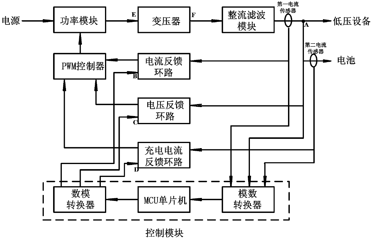
[0017] like figure 1 As shown, the vehicle power supply system includes a power supply, a PWM controller, a power module, a transformer, a rectifier filter module, a current feedback loop, a voltage feedback loop, a charging current feedback loop, and a control module; the power supply is connected to the power The input end of the module...


PUM


Abstract

The invention discloses a vehicle power supply system and a working method thereof. A power source is connected to a power module which is connected to a transformer; the transformer is connected to a rectification filtration module; the rectification filtration module is connected to a low voltage device and a battery; an MCU (Micro Controller Unit), an analog-to-digital converter and a digital-to-analog converter which collect voltage and current signals control a current feedback loop, a voltage feedback loop and a charging current feedback loop; the current feedback loop, the voltage feedback loop and the charging current feedback loop output to the input end of the a PWM (Pulse Width Modulation) controller to control the output duty ratio of the PWM controller. The vehicle power supply system and the working method thereof have the advantages of overcoming disadvantages of the prior art, guaranteeing the power demand of the vehicle low voltage device and guaranteeing the service life of the battery.

Description

technical field [0001] The invention belongs to the field of current conversion, and specifically designs a vehicle power supply system from high voltage to low voltage for vehicles and a working method thereof. Background technique: [0002] In a hybrid vehicle, the low-voltage generator is very inefficient for charging the battery. Therefore, in order to improve the fuel saving rate, the low-voltage generator will be replaced with a more efficient power supply system, that is, a DC converter. After the energy is converted, it charges the low-voltage battery and supplies power to the low-voltage system of the whole vehicle at the same time. At this point, a contradiction arises. If the power of the power supply system is too large, the charging current of the battery will be too large, which will seriously affect the life of the battery; The power demand of the system. The traditional low-voltage power supply system for vehicles is controlled by a PWM controller to genera...

Claims


Application Information

Patent Timeline
Patent Type & Authority Applications(China)
IPC IPC(8): H02M3/28H02J7/00
Inventor 何斌
Owner TIANJIN SANTROLL ELECTRIC AUTOMOBILE TECH CO LTD
Why Eureka
Try Eureka