Heating circulating pump

A heat supply cycle, pump housing technology, applied in the direction of pumps, pump elements, pump devices, etc.

Active Publication Date: 2013-12-04
GRUNDFOS MANAGEMENT AS
View PDF5 Cites 11 Cited by
  • Summary
  • Abstract
  • Description
  • Claims
  • Application Information

AI Technical Summary

Problems solved by technology

[0003] Such small to medium heating circulators are already produced in high volumes, so even the smallest improvements can mean huge savings in manufacturing and / or assembly

Method used


Image

  • Heating circulating pump
  • Heating circulating pump
  • Heating circulating pump

Examples


Embodiment Construction

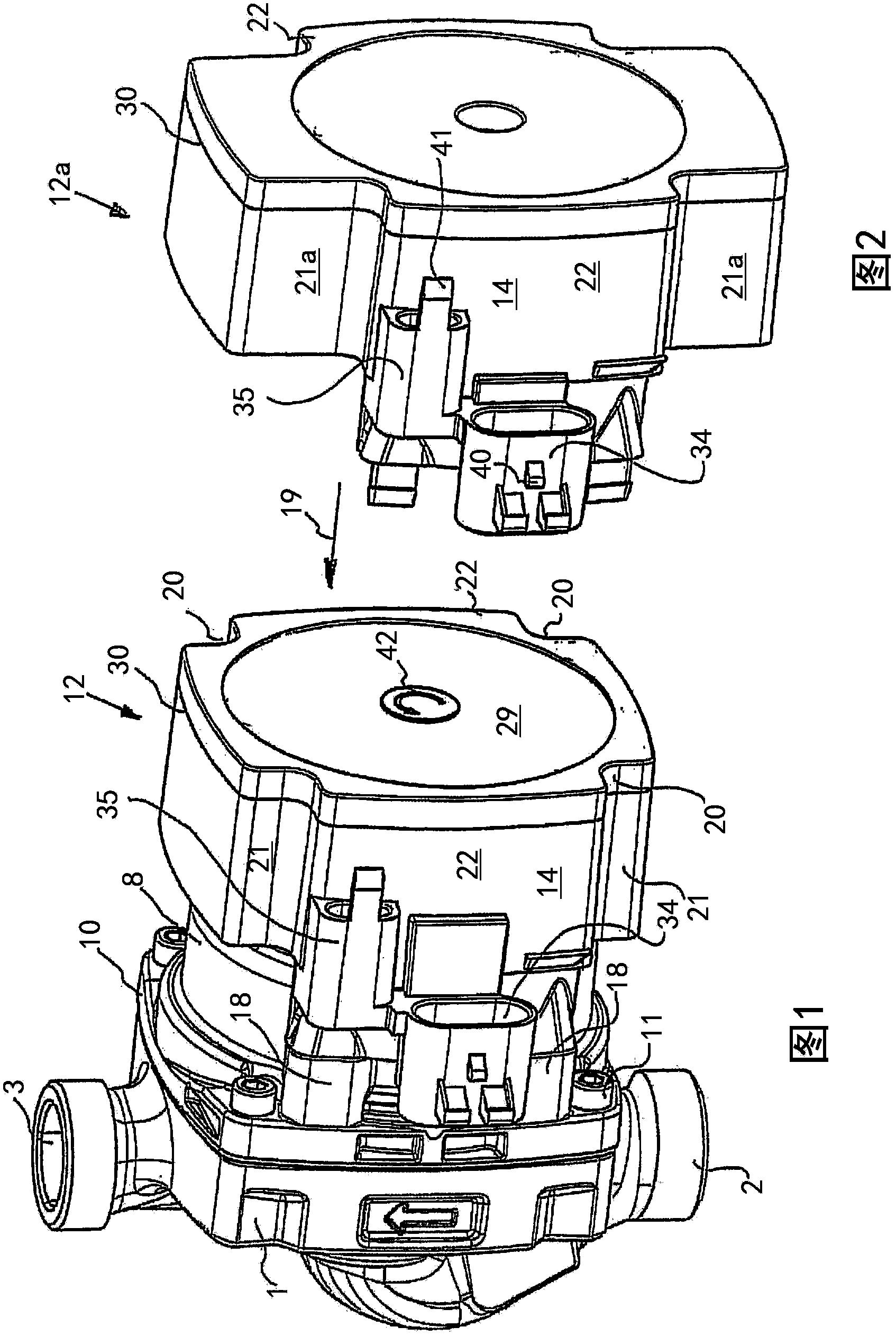
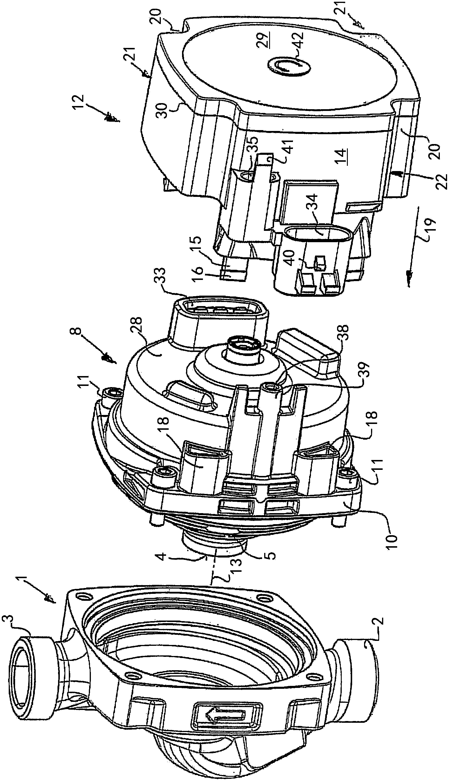
[0027] like figure 1 as well as Figure 3 to Figure 8 The heating circulation pump shown has a centrifugal pump comprising a pump housing 1 with a suction sleeve 2 and a pressure sleeve 3 and a guide channel arranged between them, which will lead from the suction The liquid from the casing 2 is fed to the suction 4 of a pump impeller 5 mounted inside the pump housing 1 , the output side of which is connected to the channel leading to the pressure casing 3 .

[0028] The heating circulation pump has an electric motor, here a wet-running electric motor, whose rotor 6 runs in a liquid-filled slot 7 . The can tube 7 is surrounded by a stator (ie a motor winding arranged around the can tube 7 ) and a motor housing 8 for accommodating the stator. The rotor 6 has an intermediate shaft 9 which extends into the pump housing 1 and carries the pump impeller 5 in order to transmit the rotational movement of the rotor 6 to the pump impeller 5 .

[0029]The motor housing 8 has a flange 1...


PUM


Abstract

The invention relates to a heating circulating pump comprising: a pump housing (1) containing a pump impeller driven by an electric motor, the stator thereof being arranged in a motor housing (8) connected to the pump housing (1); and a terminal box (12) arranged on the motor housing (8), for electrically connecting the motor winding and for receiving electrical and/or electronic components of the motor control system. The terminal box (12) consists of at least two parts that are bonded to each other, and it (12) is designed such that it is sealed from the motor and from the surrounding environment.

Description

technical field [0001] The invention relates to a heating circulation pump having the features stated in the preamble of claim 1 . Background technique [0002] Such heating circulation pumps are known in the prior art. They usually comprise a pump housing with a suction sleeve and a pressure sleeve and a pump impeller arranged in the pump housing. An electric motor is provided to drive the pump impeller, and the shaft of the electric motor carries the pump impeller. The stator surrounding the rotor is arranged in a housing which has a flange or similar connecting element on its side facing the pump housing, via which the motor housing, in particular the stator housing, is connected to the pump housing. connect. A terminal box is provided for the electrical connection of the electric motor, which is arranged on the axial side of the stator housing facing away from the pump housing. The terminal box usually also contains the motor electronics, such as a frequency converte...

Claims


Application Information

Patent Timeline
Patent Type & Authority Applications(China)
IPC IPC(8): F04D13/06F04D29/02F04D29/42H02K5/128H02K5/22
CPCH02K11/0089F04D13/064F04D13/0686H02K5/225F04D29/426F04D29/026H02K5/10F04D13/06H02K2203/03H02K11/40F05D2300/43F05D2230/232F04D13/0626F04D29/5893F04D29/5813F05D2230/20
Inventor 芬恩·马蒂森·霍耶
Owner GRUNDFOS MANAGEMENT AS
Why Eureka
Try Eureka