Metal wire drawing die seat device

A technology of metal wire and die base, applied in the direction of wire drawing dies, etc., can solve problems such as inability to draw, and achieve the effects of reducing consumables, reducing costs, and reducing usage

Inactive Publication Date: 2013-12-11
王玉凯
View PDF7 Cites 2 Cited by
  • Summary
  • Abstract
  • Description
  • Claims
  • Application Information

AI Technical Summary

Problems solved by technology

There is a mold base device for the production of ordinary copper-clad aluminum rod wires, but this is only suitable for metallurgically bonded copper-clad aluminum rod wires, and cannot form copper-clad stranded wires for high-speed railway bases that do not require metallurgical bonding The sheath penetrates the wire for drawing

Method used


Image

  • Metal wire drawing die seat device
  • Metal wire drawing die seat device
  • Metal wire drawing die seat device

Examples


Embodiment Construction

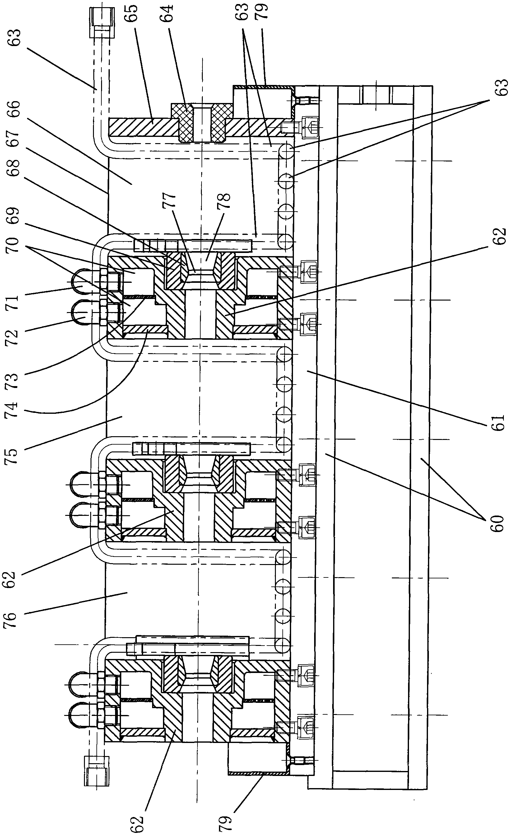
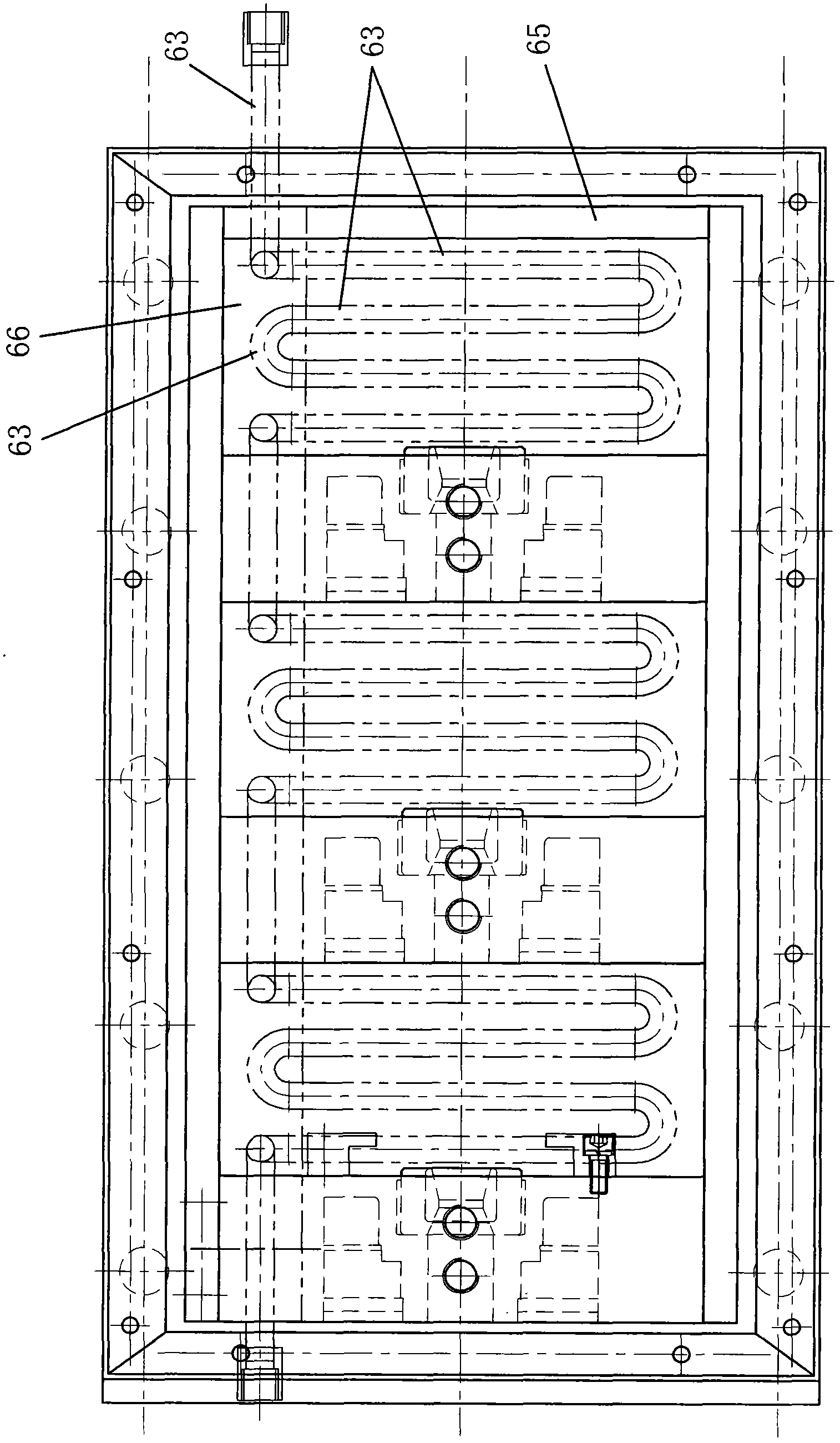
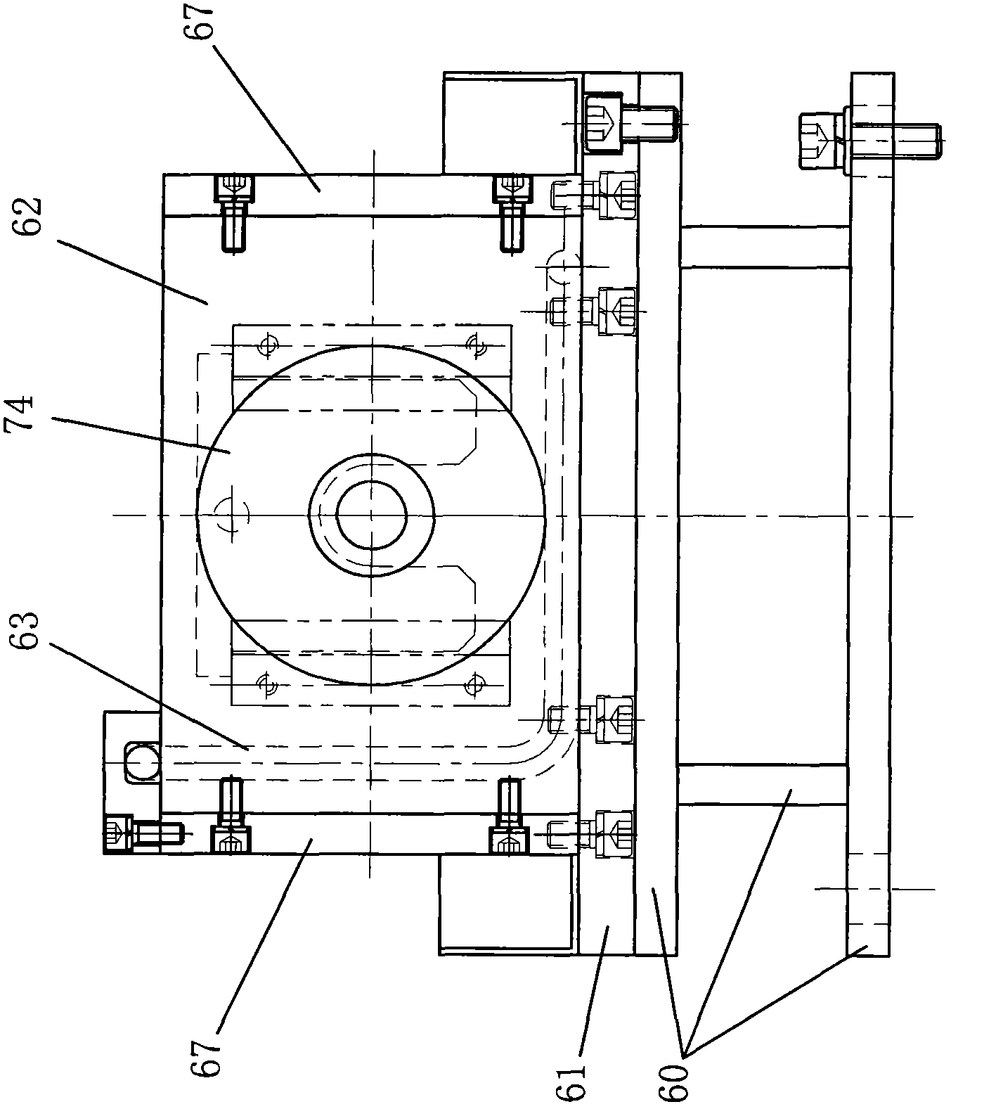
[0014] Such as figure 1 , 2 . As shown in 3: 60 is a base, and a bottom plate 61 is fixedly connected to the base 60 by bolts. On the base plate 61, three (group) die holders 62 are fixedly installed by bolts, and die cover 69 is all housed in the center hole front side concave hole of each die holder 62, and drawing die 68 is positioned in the die cover 69. A die hole 77 is arranged at the center of the drawing die 68, and a tapered hole 78 is arranged on the front side.

[0015] There are drawing oil chambers between the adjacent die bases 62 and at the front end of the die base 62 located at the front end. Each drawing oil cavity is formed by the following structure: on both sides of each die base 62, there are side plates 67 fixedly connected with the die base 62 by bolts; The center hole is inlaid with the end plate 65 of the inlet sleeve 64, and the side plates 67, end plates 65, bottom plate 62 and each mold base 62 on both sides enclose the drawing oil chamber locat...


PUM

PropertyMeasurementUnit
strengthaaaaaaaaaa
lengthaaaaaaaaaa
elongation at breakaaaaaaaaaa

Abstract

The invention discloses a metal wire drawing die seat device which comprises a bottom plate. At least two die seats are arranged on the bottom plate; a drawing die is arranged on the front side of a center hole of each die seat; drawing oil cavities are formed between the adjacent die seats and at the front end of the die seat at the most front end; the peripheries of the centers of the die seats are provided with cooling water cavities and are connected with water inlet joints and water return joints; cooling water pipes connected with a cold water supply device are arranged in the drawing oil cavities. The cooling water pipes are arranged in the drawing oil cavities, so that in the operating process, heat of oil is timely taken away by the cold water supply device to effectively cool down drawing oil, viscosity of the drawing oil is ensured and meanwhile, drawing quality is ensured.

Description

technical field [0001] The invention relates to a metal wire drawing die base device, in particular to a drawing die base device for a sheath buried underground on a railway to pass through a ground wire. Background technique [0002] The development of high-speed railway is coming fast. At present, according to the needs, there are clear requirements for the sheathed through-conductor buried under the high-speed railway foundation. The interior is made of multiple (19 or 7) soft round copper wires twisted. Conductor, the elongation at break of the soft round copper wire is not less than 25%. The structure and appearance of the conductor should meet the requirements of the second type of conductor in GB / T3956. The surface of the conductor should be smooth, free of oil, burrs, protrusions or breaks. The outer side is covered with H62 or H65 brass strip, the material state of the brass strip is soft, and the thickness of the brass strip is 1.0mm±0.05mm. The width of the coppe...

Claims


Application Information

Patent Timeline
Patent Type & Authority Applications(China)
IPC IPC(8): B21C3/14
Inventor 王玉凯宫世宝王琦
Owner 王玉凯
Why Eureka
Try Eureka