Welding equipment and technology of parts in closed cavity

A technology for welding parts and sealing cavities, which is applied in welding equipment, welding accessories, arc welding equipment, etc., can solve the problems of no corresponding welding equipment and inability to weld, and achieve the problems of inability to weld, guarantee welding quality, and expand the field of use Effect

Active Publication Date: 2016-01-27
ZHEJIANG CTB WAVEFORM STEEL WEB
View PDF8 Cites 0 Cited by
  • Summary
  • Abstract
  • Description
  • Claims
  • Application Information

AI Technical Summary

Problems solved by technology

[0003] The present invention is proposed to solve the shortcomings of the existing welding equipment and technology for parts in the closed cavity, such as the inability to weld and the lack of corresponding welding equipment, etc., and aims to provide parts in the closed cavity that can weld parts in the closed cavity Welding equipment and process

Method used


Image

  • Welding equipment and technology of parts in closed cavity
  • Welding equipment and technology of parts in closed cavity

Examples


Embodiment 1

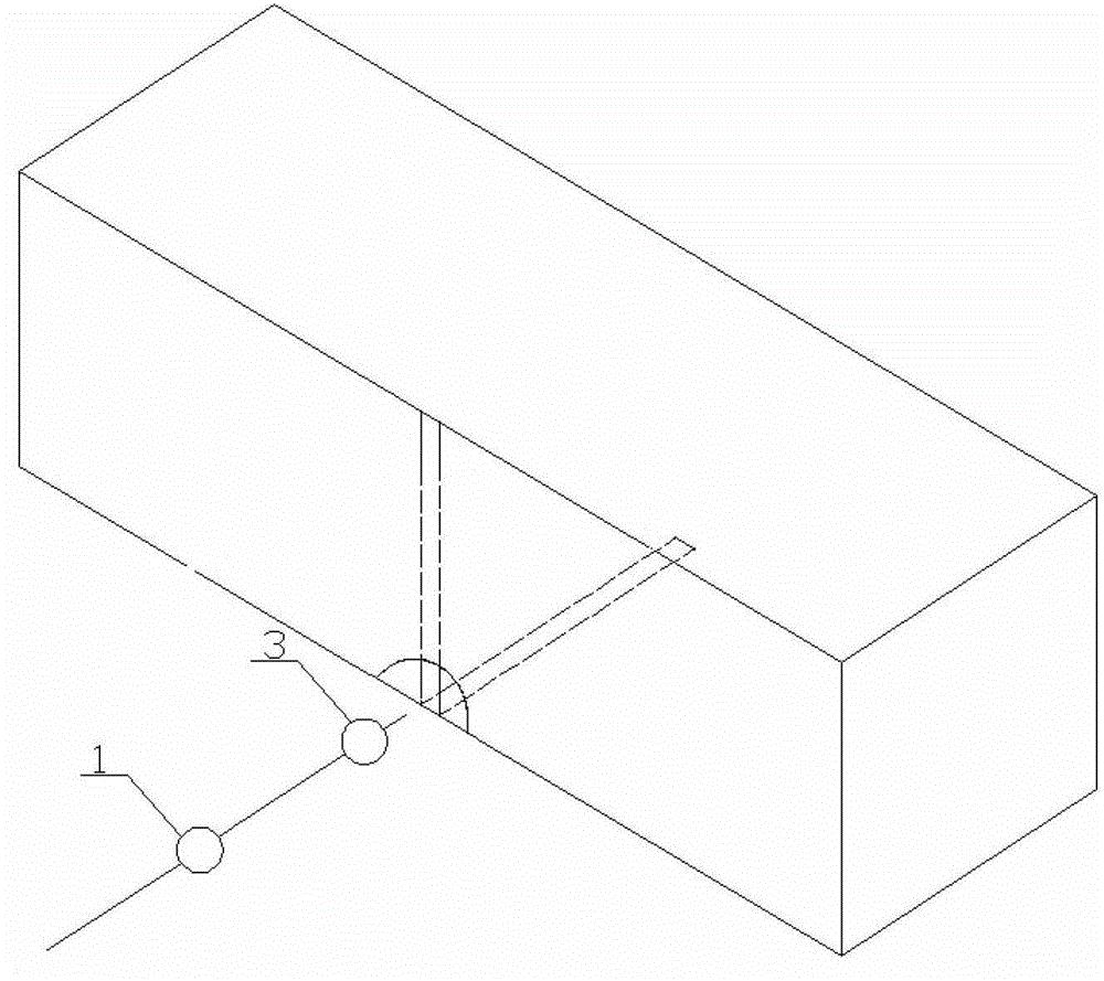
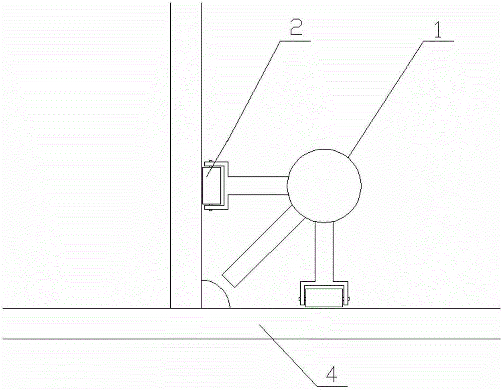
[0020] Welding equipment for parts in a closed cavity, including a welding torch 1, a two-dimensional magnetic positioning wheel 2, and a viewing mirror 3. The length of the welding torch 1 is 50%-150% of the length of the welding bead, and the two-dimensional magnetic positioning wheel 2 is set on the support of the welding torch 1. On the feet, the sight glass 3 is installed in the front of the welding torch 1.

[0021] The two-dimensional magnetic positioning wheel 2 moves on the steel plates 4 on both sides of the weld bead.

[0022] Peep mirror 3 is connected with display by wire.

[0023] The entering direction of the wire is opposite to that of the welding torch 1 .

[0024] The entry direction of the wire is equipped with a smoke absorbing device.

[0025] The welding torch 1 is a gas shielded welding machine.

Embodiment 2

[0027] The welding process of parts in a closed cavity includes the following steps:

[0028] a. There are 4 welding holes in the steel plate at both ends of the weld bead;

[0029] b. Install the cover plate and implement spot welding;

[0030] c. Flip the member so that the weld bead faces upward;

[0031] d. One end extends into the peep mirror 3 and connects with the welding torch 1 at the other end;

[0032] e. Move the sight glass 3 and the welding torch 1 to the starting welding position;

[0033] f. Carry out welding of internal parts; welding of internal parts shall be done in one time or separately from the center of the weld bead to both sides.

[0034] g. Welding hole sealing welding;

[0035] h. Cover welding.

[0036] The cross-section of the welding hole is larger than that of the welding torch and the sight glass, and the welding hole is located in a non-main structural part.

[0037] The welding quality is determined by the difference analysis method bet...


PUM


Abstract

The invention relates to equipment for welding parts in a closed cavity. The equipment comprises a welding gun (1), a two-dimensional magnetic positioning wheel (2) and inspection glass (3), wherein the length of the welding gun (1) is 50-150% that of a welding bead; the two-dimensional magnetic positioning wheel (2) is arranged on a supporting leg of the welding gun (1), and the inspection glass (3) is arranged in front of the welding gun (1). The equipment and process for welding the parts in the closed cavity can be used for realizing the welding operation in the closed cavity, effectively solving the problem that welding cannot be performed in the closed cavity and achieving revolutionary breakthrough in the welding field and enlarging the application field of the welding process; In addition, according to the process for welding the parts in the closed cavity, a flaw detection instrument is utilized, detection results before and after welding are subjected to contrastive analysis, so that the welding effect is determined, and thus the process for welding in the closed cavity can achieve effective guarantee in welding quality.

Description

technical field [0001] The invention relates to welding equipment and technology, in particular to welding equipment and technology for parts in a closed cavity. Background technique [0002] During the bridge construction process, it is difficult to realize the welding of the parts in the closed cavity and the cover plate after closing the cover plate for the parts in the closed cavity, such as the inner stiffeners of the steel box girder. When the cavity is large, an access hole is generally provided on the cover plate so that actual welding personnel can enter the cavity to carry out welding operations, but the access hole will damage the overall structure and appearance. When the cavity is small, welding operations cannot be performed. Using the traditional inner cavity welding method, not only the welding process is complicated, but also the heat equivalent generated during welding is large, which makes the main structural steel plate prone to welding defects, thus aff...

Claims


Application Information

Patent Timeline
Patent Type & Authority Patents(China)
IPC IPC(8): B23K9/16B23K9/32
Inventor 孙天明俞建峰
Owner ZHEJIANG CTB WAVEFORM STEEL WEB
Why Eureka
Try Eureka