Zero band beam layer cutting device and using method thereof

A belt layer cutting technology, applied in the field of zero-degree belt layer cutting device, can solve the problems of affecting product quality, complicated operation, and impossible completion of the plan, and achieve the effect of improving cutting efficiency

Inactive Publication Date: 2013-12-11
MESNAC
View PDF9 Cites 2 Cited by
  • Summary
  • Abstract
  • Description
  • Claims
  • Application Information

AI Technical Summary

Problems solved by technology

[0004] The ply cutting and belt layer cutting described in the above prior art belong to the same field, which solves the problems of large floor space and complicated operation
However, for the simultaneous cutting of multiple belt layers, the above scheme cannot be completed
In addition, the above scheme uses a power drive device to drive the screw to rotate, so that the disc hob device moves for cutting; during the single-circle operation of this cutting machine, the screw is prone to jamming, and the cutting head will be loose. affect the quality of the product

Method used


Image

  • Zero band beam layer cutting device and using method thereof
  • Zero band beam layer cutting device and using method thereof
  • Zero band beam layer cutting device and using method thereof

Examples


specific Embodiment approach

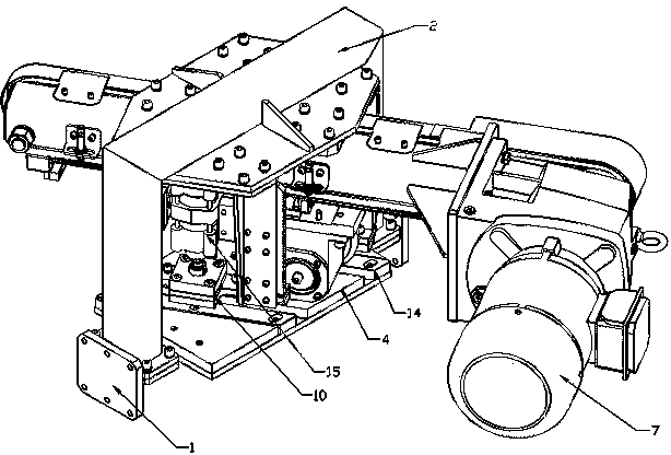
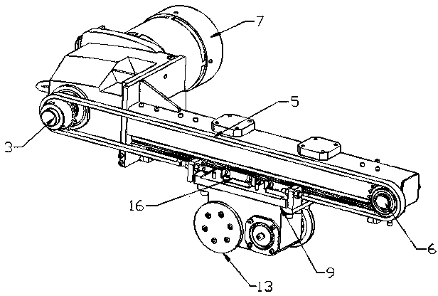
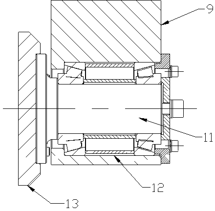
[0022] Such as figure 1 As shown, a zero-degree belt layer cutting device includes a frame, a drive mechanism installed on the frame, and a cutter assembly controlled by the drive mechanism to slide; at least two disc hobs 13 are installed on the cutter assembly.

[0023] The frame includes a cutter base frame 1 and a mounting frame 2 installed on the cutter base frame 1 .

[0024] The cutting device also includes a fixed assembly for fixing zero-degree belt layer movement, and the fixed assembly is installed on the mounting frame; the fixed assembly includes a cylinder 15 mounted on the mounting frame, and a pressure plate 10 controlled by the cylinder 15 to lift.

[0025] The cutting device also includes a knife slot that cooperates with the disc hob 13 for cutting, and the knife slot is located below the disc hob 13; The secondary cutter plate 14 is formed; the composition material of the knife groove can be changed according to the actual situation, as long as its functio...


PUM


Abstract

The invention relates to a zero band beam layer cutting device which comprises a stand, a driving mechanism and a cutter component, wherein the driving mechanism is arranged on the stand; the slide of the cutter component is controlled by the driving mechanism; the cutter component is provided with at least two disk hobs. The zero band beam layer cutting device has the beneficial effects that the at least two disk hobs are adopted for cutting at the same time, so that the working efficiency and the product quality are improved, and the device is simple to operate, small in occupied land and easy to maintain; a sliding block is driven to slide by a conveyor belt, so that the movement of the disk hobs can be realized; the zero band beam layer cutting device is easier to control and convenient to maintain.

Description

technical field [0001] The invention belongs to the technical field of truck tire cutting, and in particular relates to a zero-degree belt layer cutting device and a use method thereof. Background technique [0002] On the existing all-steel truck tire building machines at home and abroad, most of them adopt zero-degree belt layer coiling, transport it to the belt layer through the conveying device, and cut it after lamination. The cutting method is driven by the motor to move up and down. The guillotine is used to realize the cutting. This method has a complicated structure, takes up a lot of space, has low efficiency and poor precision. [0003] In the Chinese patent literature, the patent number is ZL200820187961.8, and the name is a utility model of a giant engineering radial tire thick steel wire disc knife cutting machine. It discloses a scheme, including a frame, a beam is arranged above the frame, and a beam is arranged below the frame. A bottom knife rest is provi...

Claims


Application Information

Patent Timeline
Patent Type & Authority Applications(China)
IPC IPC(8): B26D1/18B26D5/08B26D7/26
CPCB29D30/46
Inventor 王延书贾海玲熊小伟
Owner MESNAC
Why Eureka
Try Eureka