Comprehensive monitoring method of urban railway traffic network facilities

A technology for urban rail transit and rail transit road network, applied in the fields of railway traffic management, railway car body parts, railway signal and safety, etc., can solve the problems that cannot meet the needs of the road network center for monitoring line equipment, and achieve network saving The effect of laying costs, reducing the amount of data transmission, and saving bandwidth resources

Active Publication Date: 2013-12-11
HENAN SPLENDOR SCI & TECH
View PDF5 Cites 7 Cited by
  • Summary
  • Abstract
  • Description
  • Claims
  • Application Information

AI Technical Summary

Problems solved by technology

[0005] Obviously, the current equipment status monitoring method cannot

Method used


Image

  • Comprehensive monitoring method of urban railway traffic network facilities
  • Comprehensive monitoring method of urban railway traffic network facilities
  • Comprehensive monitoring method of urban railway traffic network facilities

Examples


Embodiment 1

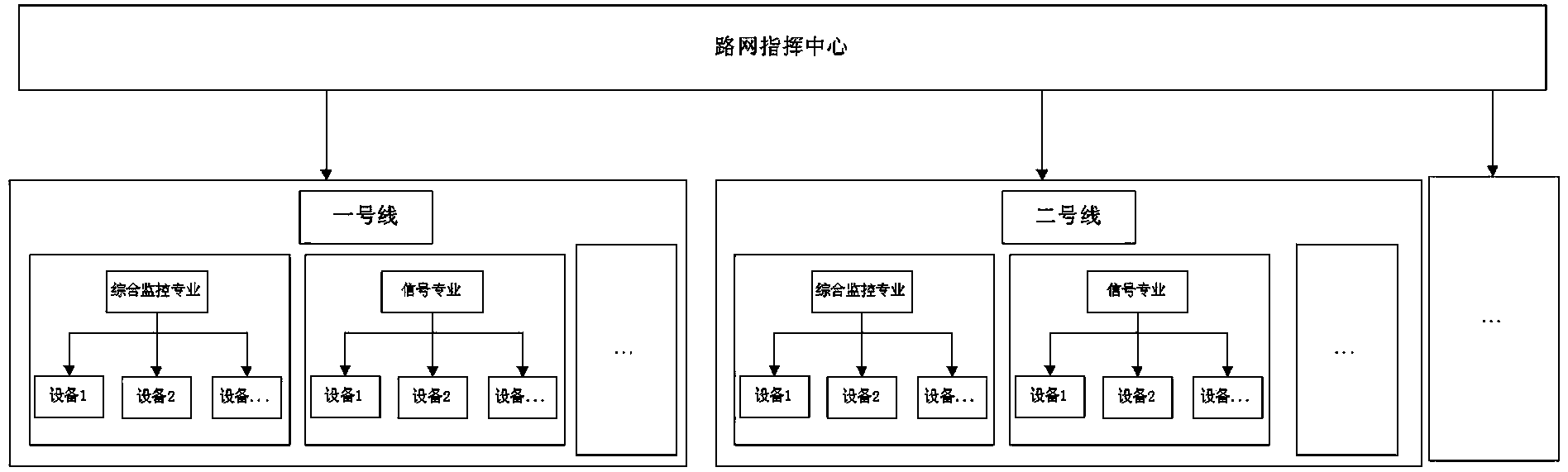
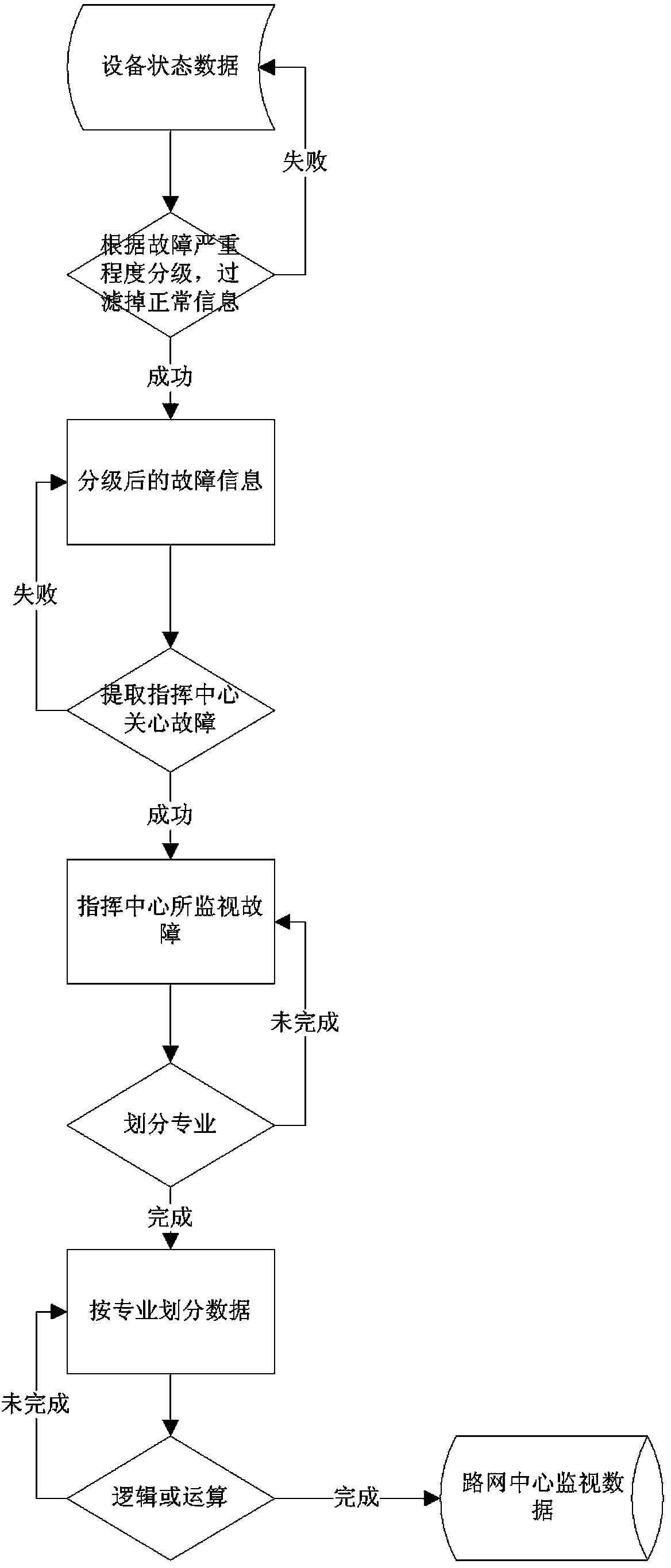
[0024] see Figure 2 ~ Figure 4 , the urban rail transit road network equipment comprehensive monitoring method of the present invention, for acquiring real-time state information of each line equipment from the rail transit road network data center, including normal state and fault state; performing data classification, data screening and data logic operation on the equipment state data ,in:

[0025] Data classification: It is to divide all the equipment status information obtained according to the five majors of comprehensive monitoring, signal, automatic fare collection, communication and vehicle; or, according to the system, it is divided into environment and equipment monitoring system (BAS), fire alarm system (FAS), power monitoring system (PSCADA), access control system (ACS), screen door system (PSD), closed circuit television system (CCTV), broadcasting system (PA), passenger guidance information system (PIS);

[0026] Data screening: Filter the data after the divis...

Embodiment 2

[0030] The urban rail transit road network equipment comprehensive monitoring method of this embodiment is different from Embodiment 1 in that: further, when performing data logic operations, when the logical state is a failure, by associating the logical state with the actual state, It can be traced back to which line equipment the actual alarm record caused the logical state to be fault.

Embodiment 3

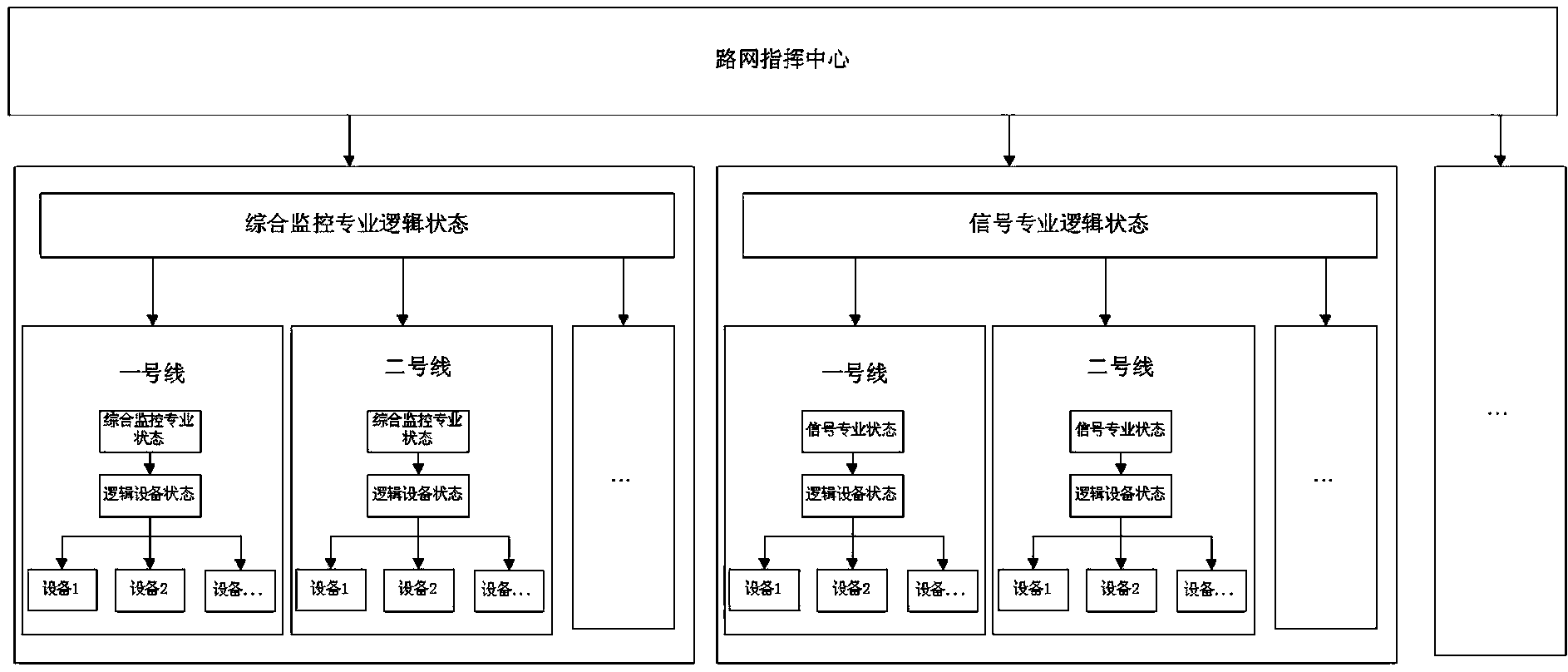
[0032] see figure 2 , image 3 , the urban rail transit road network equipment comprehensive monitoring method of this embodiment is different from embodiment 1 or embodiment 2, further, such as Figure 4 As shown, the data logic operation includes: taking the line as the unit, performing logical operations on the equipment belonging to each line, and the result of the operation is used as the state of the line; The result of logic operation and re-operation is the professional status that needs to be monitored.


PUM


Abstract

The invention relates to a monitoring method of urban railway traffic network facility states, and provides the comprehensive monitoring method of urban railway traffic network facilities. The monitoring method comprises the steps of obtaining real-time state information of each line facility form a railway traffic network data center, then performing classification, screening and logical operation on the status data of the facilities and dividing all the obtained state information of the facilities according to specialty or systems; filtering the data after specialty division and dividing the state information three alarm ranks according to fault severity; setting the alarm rank of the facility to be monitored by the traffic network data center; according to the data classification about the specialty to which the fault information of the facility belongs, setting the alarm rank of the facility to be monitored by the traffic network data center; if one or more pieces of alarm information conform to the alarm ranks in the specialty or the system, determining the current logic state of the specialty or the system as a fault. The method mainly aims at achieving the purpose of comprehensively monitoring the states of multiple lines, multiple specialties and multiple facilities by the railway traffic network center.

Description

technical field [0001] The invention relates to a method for monitoring equipment status, in particular to a method for comprehensively monitoring urban rail transit road network equipment. Background technique [0002] With the acceleration of domestic urban rail transit construction, more and more cities have multiple rail transit lines. Each traffic line has an independent construction control center, so that each city has several line control centers. With the formation of a multi-line, multi-operator network transportation pattern, it is difficult to adapt to multiple Lines, network transport coordination under multi-operator conditions, emergency handling, etc. In recent years, more and more cities have begun to establish rail transit road network centers. How to monitor the operating status of different lines, different stations, and different equipment in the center in real time is particularly important. [0003] At present, the monitoring method of the equipment ...

Claims


Application Information

Patent Timeline
IPC IPC(8): B61L27/00
Inventor 翟军锋马子彦许新伟李建峰
Owner HENAN SPLENDOR SCI & TECH
Why Eureka
Try Eureka