
Vibration reduction and explosion reduction split type imported energy dissipation device

An energy-dissipating, split-type technology, applied in water conservancy projects, marine engineering, coastline protection, etc., can solve problems such as vibration of the middle partition wall, high water flow velocity, and the impact of surrounding residents, so as to improve safety and operational safety. performance, weakening the risk factor of cavitation damage, and avoiding the effect of cavitation damage

Active Publication Date: 2015-08-12
SICHUAN UNIV
View PDF7 Cites 0 Cited by
  • Summary
  • Abstract
  • Description
  • Claims
  • Application Information

AI Technical Summary

Problems solved by technology

[0003] Existing differential or non-differential split-type inlet energy dissipators, the middle partition wall of the water flow chute section is a cantilever structure (see CN101215828A, CN101624818B), so there are the following problems: 1. The vibration problem of the middle partition wall (for the middle partition The safety impact of the wall itself), due to the weak shear, bending and vibration resistance of the partition wall of the cantilever structure, it usually requires a higher amount of reinforcement to meet its stability requirements
But despite this, in the case of large single width and high head flow, due to the thin partition wall in the cantilever structure, the flow rate of the water stream passing through the high and low holes on both sides is high and turbulent, which can easily cause the middle The vibration or even resonance of the partition wall poses a great threat to the safety and stability of the partition wall; 2. The impact on the safety of surrounding buildings, in the case of large single width and high water head flow, when the water flow crosses the partition wall It is easy to engulf a large amount of air and form a huge air bag. After the air bag enters the stilling pool, it floats up under the action of buoyancy, and is squeezed, sheared and strongly pulsated by the surrounding water body, so it explodes suddenly near the water surface, causing the stilling pool to rise This air pressure pulsation is extremely detrimental to the safety and stability of the side wall of the stilling pool and the surrounding light buildings, affects the surrounding residents, and even causes the vibration of the doors and windows of the building and the breaking of glass, etc.

Method used


Image

  • Vibration reduction and explosion reduction split type imported energy dissipation device
  • Vibration reduction and explosion reduction split type imported energy dissipation device
  • Vibration reduction and explosion reduction split type imported energy dissipation device

Examples


Embodiment 1

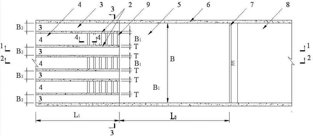
[0036] The split-type imported energy dissipator for vibration reduction and explosion reduction in this embodiment is a differential split-type imported energy dissipator, and its structure is as follows figure 1 , Figure 10 , Figure 11 with Figure 15 As shown, it includes a water flow chute section, a stilling basin 5 connected to the water flow chute section, and an apron 7 connected to the stilling basin. Hole drain 3 and middle hole drain 4, a connecting beam 9 is arranged between the two groove walls of each middle hole drain, and the two ends of the connecting beam are respectively fixed on the two groove walls of the middle hole drain 4 , connect the partition walls. There are 5 surface hole drains, the width of which is B 2 =4m, there are 4 middle-hole chute, and its width B 1 =6m, middle partition wall thickness T=3m, stilling basin width B=52m, depth H from the outlet of surface hole chute to stilling basin bottom plate 3 =16m, the depth H from the outlet o...

Embodiment 2

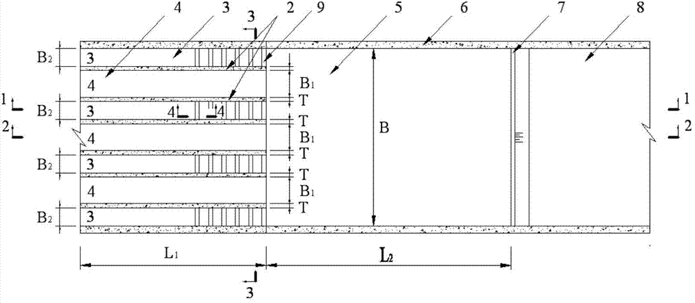
[0039] The split-type imported energy dissipator for vibration reduction and explosion reduction in this embodiment is a differential split-type imported energy dissipator, and its structure is as follows figure 2 , Figure 9 , Figure 12 with Figure 15 As shown, it includes a water flow chute section, a stilling basin 5 connected to the water flow chute section, and an apron 7 connected to the stilling basin. Hole drain 3 and middle hole drain 4, a connecting beam 9 is arranged between the two groove walls of each surface hole drain, and the two ends of the connecting beam are respectively fixed on the two groove walls of the surface hole drain 3 , connect the partition walls. There are 5 surface hole drains, the width of which is B 2 =4m, there are 4 middle-hole chute, and its width B 1 =6m, middle partition wall thickness T=3m, stilling basin width B=52m, depth H from the outlet of surface hole chute to stilling basin bottom plate 3 =16m, the depth H from the outlet...

Embodiment 3

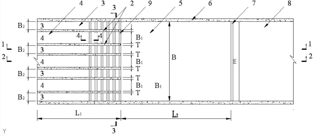
[0042] The split-type imported energy dissipator for vibration reduction and explosion reduction in this embodiment is a non-differential split-type imported energy dissipator, with a structure such as image 3 , Figure 4 , Figure 5 , Figure 8 with Figure 14 As shown, it includes a water flow chute section, a stilling basin 5 connected to the water flow chute section, and an apron 7 connected to the stilling basin. Hole discharge groove 3 and middle hole discharge groove 4, connecting beam 9 is arranged between the two groove walls of each surface hole discharge groove 3 and the middle hole discharge groove, and the two ends of the connection beam are respectively fixed on the surface hole discharge groove 3 and the two groove walls of the middle hole discharge groove 4, the middle partition wall is connected. There are 5 surface hole drains, the width of which is B 2 =4m, there are 4 middle-hole chute, and its width B 1 =6m, middle partition wall thickness T=3m, sti...


PUM


Abstract

The invention discloses a vibration and explosion reducing array type inlet energy dissipater which comprises a water flow discharge chute section, a stilling pool connected with the water flow discharge chute section and an apron connected with the stilling pool, wherein the water flow discharge chute is divided into a surface hole discharge chute and a middle hole discharge chute in spaced arrangement by a middle partition wall; the two side surfaces of the middle partition wall are the chute walls of the surface hole discharge chute and the middle hole discharge chute respectively; a connection beam is arranged between the two chute walls of the surface hole discharge chute or / and the middle hole discharge chute; the two ends of the connection beam are respectively fixed on the two chute walls of the surface hole discharge chute or / and the middle hole discharge chute to connect the middle partition wall. The energy dissipater disclosed by the invention can be used for reducing the vibration caused by a weak cantilever structure of the middle partition wall and reduce the influence of burst of an air bag wrapped by water flow on the safety of the buildings around.

Description

technical field [0001] The invention belongs to flood discharge and energy dissipation facilities, in particular to a vibration-reduction and explosion-reduction split-type imported energy dissipation facility for high water head and large single-width flow. Background technique [0002] The split-type imported energy dissipator is a flood discharge and energy dissipation facility used under the condition of high water head and large single-width flow, including the water flow chute section, the stilling pool connected to the water flow chute section, and the protection tank connected to the stilling pool. The water flow chute section is divided into alternately arranged surface chute (high chute) and middle chute (low chute) by the middle partition wall. According to whether the depths from the outlet of the surface hole discharge chute (high discharge chute) and the middle hole discharge chute (low discharge chute) to the bottom plate of the stilling tank are equal, it can...

Claims


Application Information

Patent Timeline
Patent Type & Authority Patents(China)
IPC IPC(8): E02B8/06
Inventor 张建民许唯临彭勇刘善均王韦曲景学邓军田忠张法星周茂林聂境
Owner SICHUAN UNIV
Learn More