
Eureka
For R&D, Eureka makes reading and utilizing patents & technical documents easy.
Eureka AIR
Designed for self-driven R&D workflows. Generate viable solutions, solve complex R&D challenges, empower your innovation with AI.

Eureka Materials
Designed for material experts only. Revolutionize your material R&D, from search, analyze, to developing new materials.

TechResearch
Generate reliable direction feasibility study reports for your R&D in just a few steps.

TechSeek
Discover and master advanced knowledge NOW. Basics, ideas, possibilities, all at once.

TechMind
As an expert in R&D Theories, TechMind can generates customized viable solutions instantly.

TechRisk
Analyze your overall solution with one click, know your potential R&D risks in advance.

TechMonitor
Get weekly tech updates, stay abreast of the latest tech innovations and key insights.
Turbine stator for turbine drill
A technology of turbo drilling tools and turbines, applied in drilling tools, drilling equipment, earth-moving drilling, etc., can solve the problems of easy breakage of blades and insufficient utilization of liquid potential energy, and achieve long service life, high potential energy utilization rate, and high efficiency. Effect
- Summary
- Abstract
- Description
- Claims
- Application Information
AI Technical Summary
Problems solved by technology
Method used
Image

Examples
Embodiment
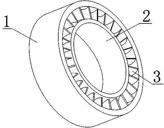
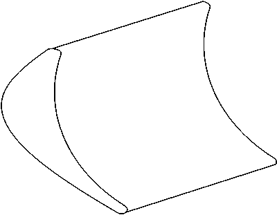
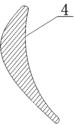
[0018] see figure 1 , figure 2 and image 3 , a turbine stator for a turbodrill, including an inner ring 2 and an outer ring 1 sleeved at the outer end of the inner ring 2, the inner ring 2 and the outer ring 1 are connected by a set of stator blades, and the set of stator blades consists of several The stator blades 3 with a crescent-shaped cross section are formed, and the stator blades 3 are evenly distributed between the inner ring 2 and the outer ring 1 with the central axis of the inner ring 2 as the symmetrical axis, and the inner arc surface of the stator blades 3 is the working surface. Surface 4.
[0019] There are 16-32 stator blades 3 .
[0020] The horizontal distance between any two adjacent stator blades 3 is greater than 12 millimeters and less than 21 millimeters.
[0021] The arc length of the working surface 4 of the stator blade 3 is 1-1.2 times of the horizontal pitch.
[0022] The radian of the working surface 4 of the stator blade 3 is 80°-100°.
...
PUM
 Abstract
Description
Claims
Application Information
 - R&D Engineer
- R&D Manager
- IP Professional
- Industry Leading Data Capabilities
- Powerful AI technology
- Patent DNA Extraction
Browse by: Latest US Patents, China's latest patents, Technical Efficacy Thesaurus, Application Domain, Technology Topic, Popular Technical Reports.
© 2024 PatSnap. All rights reserved.Legal|Privacy policy|Modern Slavery Act Transparency Statement|Sitemap|About US| Contact US: help@patsnap.com