Cylindrical coordinate measuring machine

A measuring machine, cylindrical coordinate technology, applied in the direction of measuring devices, instruments, etc., can solve the problems of horizontality affecting the movement of the pulley body, reducing the measurement accuracy, and changing the force of the rotating shaft system.

Active Publication Date: 2013-12-11
API ZC PRECISION INSTUMENT CO LTD
View PDF5 Cites 12 Cited by
  • Summary
  • Abstract
  • Description
  • Claims
  • Application Information

AI Technical Summary

Problems solved by technology

[0005] The improved cylindrical coordinate measuring machine of the present invention mainly has the following problems: first, when the trolley body moves, the torque borne by the measuring cross arm will change, resulting in a corresponding slight change in the deformation of the measuring cross arm, and finally Affect the levelness of the movement of the tackle body; second, in the case of using the central positioning device, to ensure the accuracy of the cylindrical coordinate measuring machine, it is naturally required that the positioning center of the central positioning device coincides with the central axis of the rotating shaft system; However, due to the rotation of the measuring cross arm, the counterweight cross arm and the reciprocating motion of the trolley body, the force on the rotating shaft system will change, which will easily affect the coaxiality between the positioning center of the center positioning device and the central axis of the rotating shaft system , thereby reducing the measurement accuracy

Method used


Image

  • Cylindrical coordinate measuring machine
  • Cylindrical coordinate measuring machine
  • Cylindrical coordinate measuring machine

Examples


Embodiment 1

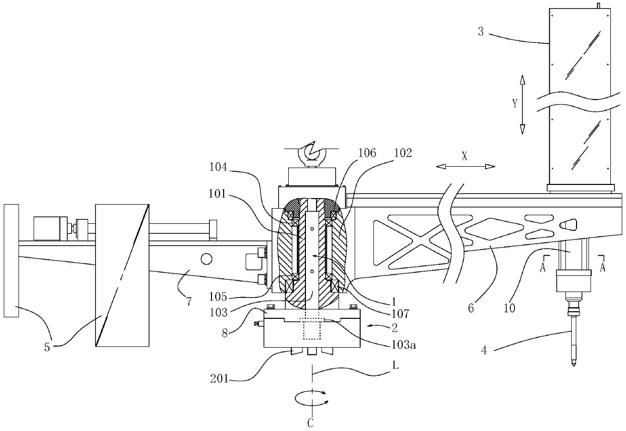
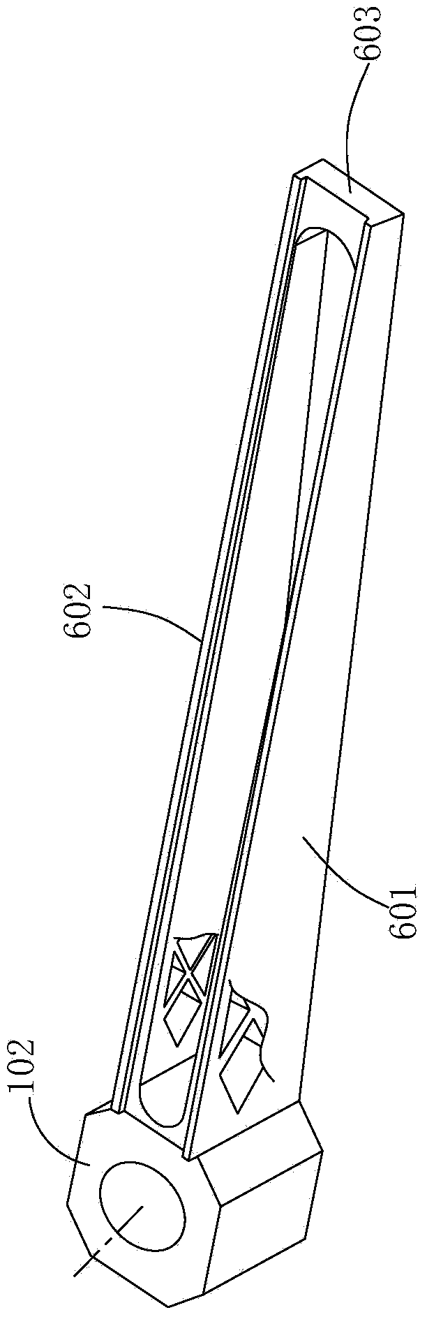
[0028] Will image 3 After the shown cast measuring cross arm 6 is installed on the rotating shaft system 1, its guide surface is processed, so that the guide surface on the first support part 601 and the second support part 602 forms an included angle with the horizontal plane of 15 " plane, and then the block body 3 is installed, and like this, the guide track to the block body 3 is formed as a straight line with a horizontal plane angle of 15 ". Verification shows that the above structure can ensure that the levelness of the movement of the tackle body 3 is within 0.1mm / 1000mm (that is, the vertical runout of the tackle body 3 is within 0.1mm for every 1000mm running of the tackle body).

Embodiment 2

[0030] Will image 3 After the shown cast measuring cross arm 6 is installed on the rotating shaft system 1, its guide surface is processed so that the guide surface on the first support part 601 and the second support part 602 forms an angle with the horizontal plane of 50 " plane, and then the block body 3 is installed, and like this, the guide track to the block body 3 is formed as a straight line with a horizontal plane angle of 50 ". Verification shows that the above structure can ensure that the levelness of the movement of the tackle body 3 is within 0.08mm / 1000mm (that is, the vertical runout of the tackle body 3 is within 0.08mm every time the tackle body 3 runs 1000mm).

Embodiment 3

[0032] Will image 3 After the shown cast measuring cross arm 6 is installed on the rotating shaft system 1, its guide surface is processed so that the guide surface on the first support part 601 and the second support part 602 forms an angle with the horizontal plane of 30 " plane, and then the block body 3 is installed, and like this, the guide track to the block body 3 is formed as a straight line with a horizontal plane angle of 30 ". Verification shows that the above structure can ensure that the levelness of the movement of the tackle body 3 is within 0.05mm / 1000mm (that is, the vertical runout of the tackle body 3 is within 0.05mm for every 1000mm running of the tackle body).


PUM


Abstract

The invention discloses a cylindrical coordinate measuring machine which is high in measuring precision. The cylindrical coordinate measuring machine comprises a rotation shaft system, a sliding car body, a measuring head unit and a counter weight device. The rotation shaft system is arranged on a base provided with a center positioning device, and the two sides of the rotation shaft system are provided with a measuring cross arm and a counter weight cross arm respectively. The sliding car body is movably arranged on the measuring cross arm and can move in the radial direction of the rotation shaft system through keeping of a first motion guiding mechanism. The measuring head unit is movably arranged on the sliding car body and can move in the direction parallel to the center axis of the rotation shaft system. The rotation shaft system comprises a main shaft and a main shaft sleeve which is connected with the main shaft in a rotating and matched mode. The measuring cross arm and the counter weight cross arm are arranged on the two sides of the main shaft sleeve respectively, and the base is arranged at the lower end of the main shaft. In addition, the guiding track of the first motion guiding mechanism on the measuring cross arm inclines upwards in the radial direction away from the rotation shaft system, and therefore variation of the deformation of the measuring cross arm can be compensated when the sliding car body moves.

Description

technical field [0001] The invention relates to a measuring device, in particular to a cylindrical coordinate measuring machine. Background technique [0002] Cylindrical coordinate measuring machine is a digital geometric quantity measuring instrument that uses sensing technology and electronic technology to measure the coordinates of cylindrical coordinate system objects (hereinafter referred to as the measured object). It is used to measure the X, Y and C axis coordinates of the surface of the measured object. In order to determine the relevant parameters of the measured object. Cylindrical coordinate measuring machines are currently mainly used in manufacturing industries such as ships, aviation, and hydropower equipment to measure workpieces with complex spatial structures and shapes, such as the measurement of propeller blade pitch. [0003] The structure of a cylindrical coordinate measuring machine to be improved in the present invention mainly includes: a rotating ...

Claims


Application Information

Patent Timeline
Patent Type & Authority Applications(China)
IPC IPC(8): G01B21/00
Inventor 刘宁黄朝胜王伟
Owner API ZC PRECISION INSTUMENT CO LTD
Why Eureka
Try Eureka