
Ring screen showing or projecting system unit based on two anisotropy fish-eye lenses

An anisotropic, fish-eye lens technology, applied in projection devices, wide-screen photography, photography, etc., can solve the problems of difficulty in taking into account functional units at the same time, a large number of projectors, and complicated processes and engineering configurations.

Active Publication Date: 2013-12-11
秦皇岛视听机械研究所有限公司
View PDF7 Cites 9 Cited by
  • Summary
  • Abstract
  • Description
  • Claims
  • Application Information

AI Technical Summary

Problems solved by technology

[0006] In view of the above-mentioned status quo, the present invention aims to solve the problem that the existing ring screen projection / projection functional units are difficult to simultaneously take into account the large field of view ratio and high pixel conversion efficiency, and to solve the problem of combining multi-functional units to splice and project large field of view ratios compared to ring screens or full rings. There are many problems that need to be projected / projectors on the screen, the process and engineering configuration are cumbersome and complex, and it cannot be miniaturized or large-scaled. However, it provides a functional unit that can form a large field of view ratio and has a high pixel conversion efficiency. A ring-screen projection / projection system unit based on a ditropic fisheye lens

Method used

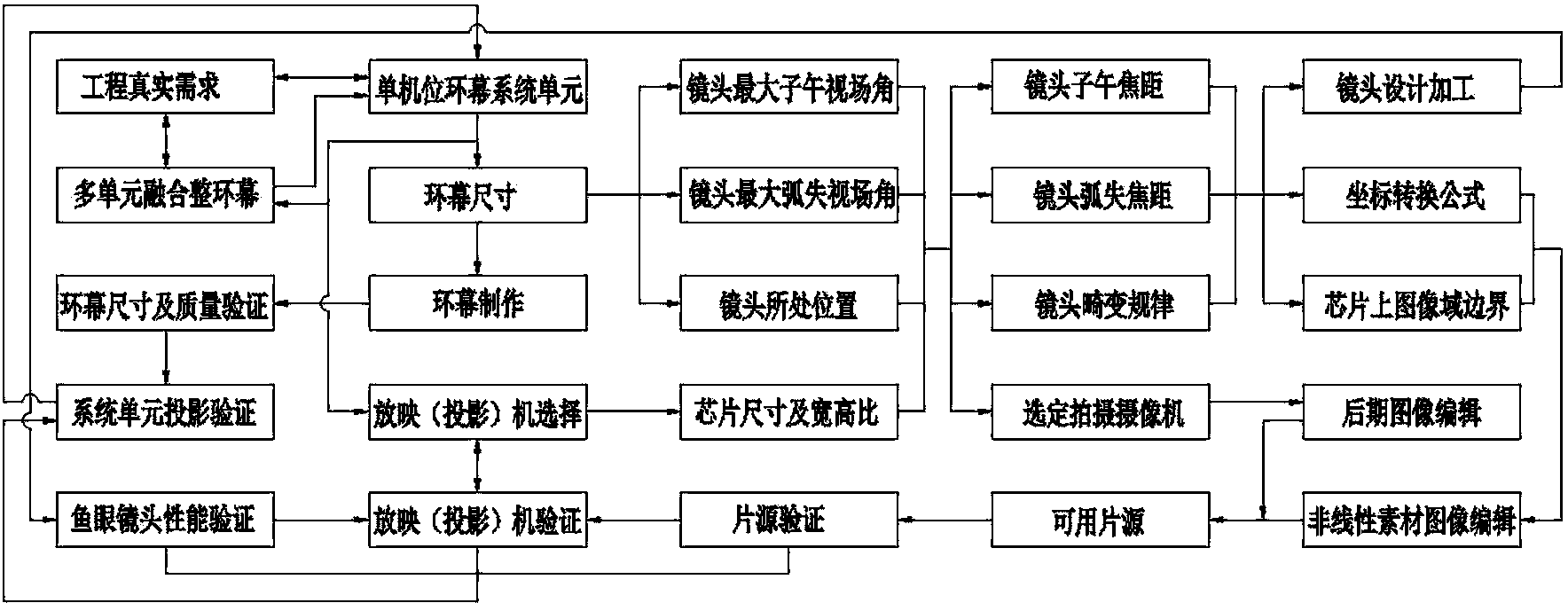
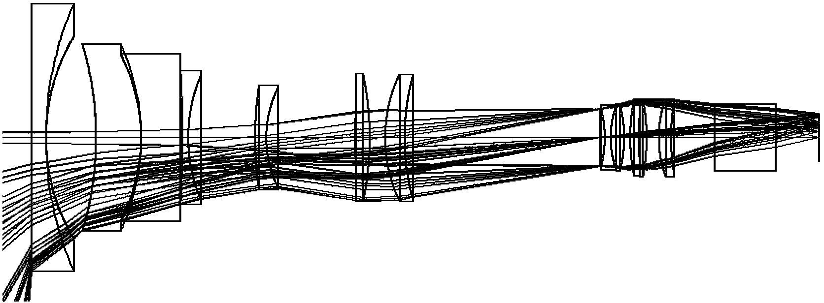

Image

  • Ring screen showing or projecting system unit based on two anisotropy fish-eye lenses
  • Ring screen showing or projecting system unit based on two anisotropy fish-eye lenses
  • Ring screen showing or projecting system unit based on two anisotropy fish-eye lenses

Examples


Embodiment Construction

[0046] The present invention will be further described below in conjunction with the accompanying drawings and embodiments.

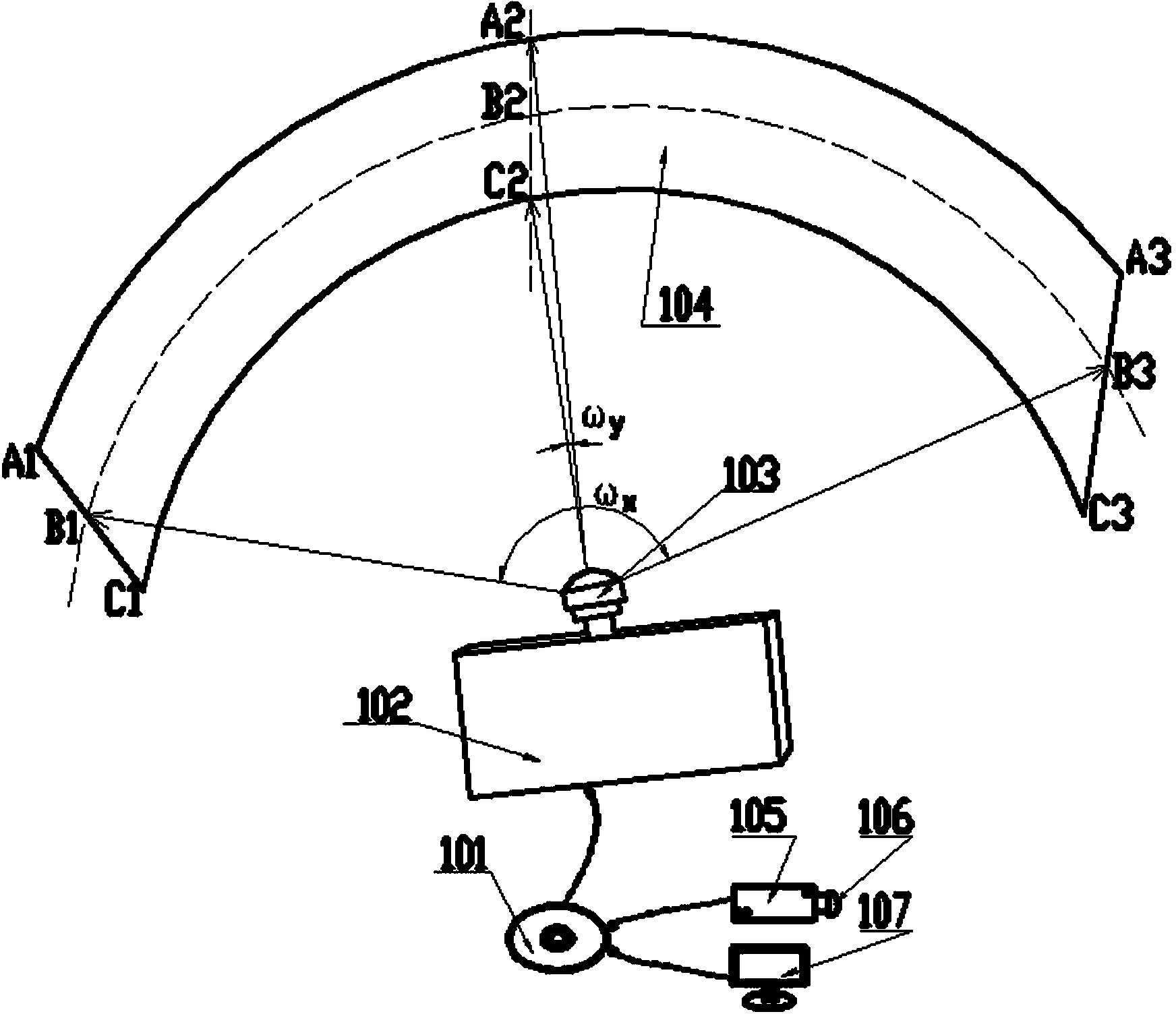
[0047] Such as figure 1 Shown is a ring-screen projection / projection system unit based on a ditropic fisheye lens. It includes a screening / projection functional unit and a film source production unit. The projection / projection functional unit of the present embodiment has a player 101, which establishes a digital signal connection with a digital projection / projector 102, and a ditropic fisheye lens 103 is installed on the digital projection / projector 102. , corresponding to the front of the dichroic fisheye lens 103, a ring screen 104 is arranged to form a configuration of functional units. In this embodiment, the four vertices of the ring curtain 104 are respectively A1, C1, A3, and C3, and the boundary of the ring curtain 104 is composed of two circular arcs A1A2A3, C1C2C3 and two straight lines A1-B1-C1, A3-B3-C3 surrounded together. The origin B...


PUM

PropertyMeasurementUnit
Central angle rangeaaaaaaaaaa

Abstract

The invention discloses a ring screen showing or projecting system unit based on two anisotropy fish-eye lenses. The ring screen showing or projecting system unit based on the two anisotropy fish-eye lenses comprises a ring screen showing or projecting function unit and a ring screen projecting film source manufacturing unit. Showing or projecting lenses are the two anisotropy fish-eye lenses which are novel and can achieve a specific object-image mapping relationship. The lenses are used for constructing the function unit and under the condition of high pixel conversion efficiency, a single showing or projecting machine can perform high-efficiency showing or projecting on a ring screen with the maximum central angle of 190 degrees and the maximum field of view ratio of 10:1. The requirements for showing or projecting of ring screens with different field of view ratios can be met through combination of the function unit and perfect pictures can be projected on a whole ring screen with the central angle of 360 degrees by combining and using the mature picture merging and splicing technology. Configuration in ring screen image engineering is simplified, difficulty of installation, debugging and later-stage maintenance in the engineering is reduced, reliability of a system is improved and the ring screen showing or projecting system unit based on the two anisotropy fish-eye lenses is applicable to a cinema, an exhibition hall and is more suitable for constructing a small desk-mounted displaying system.

Description

technical field [0001] The present invention relates to a digital image ring-screen projection / projection system unit, in particular to a device for projection / projection based on a ditropic fisheye lens combined with a digital projection / projector and a player for circular and similar circular screens The projection / projection system unit can be used to actually construct a projection / projection project with a ring screen as the projection object, such as a ring screen theater, a ring screen exhibition hall, and a small table-top ring screen rear projection TV. It belongs to the application of non-similar ultra-wide-angle optical imaging technology and computer image processing technology in the field of film and television. Background technique [0002] The ring screen is a screen whose shape is or approximates to a complete ring or a partial ring. The surface structure of this type of screen belongs to the double quadric surface type, and it has different origins in two d...

Claims


Application Information

Patent Timeline
IPC IPC(8): G03B21/56G03B37/04G03B35/18G02B13/06G03B30/00
Inventor 陈琛宋涛于国辉刘宵禅
Owner 秦皇岛视听机械研究所有限公司
Learn More