
Start circuit and voltage stabilizing circuit with start circuit

A technology of starting circuit and voltage stabilizing circuit, which is applied in the direction of adjusting electric variables, control/regulating systems, instruments, etc., can solve problems such as changing, starting circuit bias voltage is not stable enough, affecting the stability of reference output voltage Vbg, etc., to achieve Effects of improving performance, improving stability and accuracy

Active Publication Date: 2015-01-07
SILLUMIN SEMICON CO LTD
View PDF5 Cites 0 Cited by
  • Summary
  • Abstract
  • Description
  • Claims
  • Application Information

AI Technical Summary

Problems solved by technology

However, the bias voltage of the general start-up circuit is not stable enough and will change with changes in temperature and manufacturing process, which will affect the stability of the power supply voltage VDD and further affect the stability of the reference output voltage Vbg of the bandgap reference source

Method used


Image

  • Start circuit and voltage stabilizing circuit with start circuit
  • Start circuit and voltage stabilizing circuit with start circuit
  • Start circuit and voltage stabilizing circuit with start circuit

Examples


Embodiment Construction

[0037] The start-up circuit and the voltage stabilizing circuit with the start-up circuit provided by the present invention will be further described in detail below in conjunction with the accompanying drawings and specific embodiments. Advantages and features of the present invention will be apparent from the following description and claims. It should be noted that all the drawings are in very simplified form and use imprecise ratios, which are only used for the purpose of conveniently and clearly assisting in describing the embodiments of the present invention.

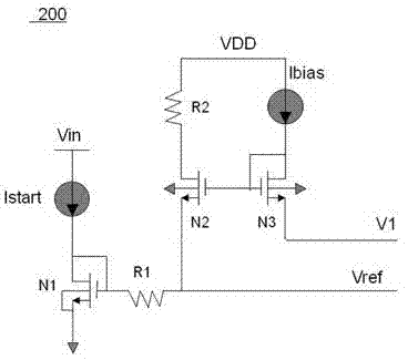
[0038] see figure 1 , figure 1 The circuit structure diagram of the starting circuit provided for an embodiment of the present invention, such as figure 1 As shown, the startup circuit 200 provided by the present invention includes a startup current source Istart, a first NMOS transistor N1, a first resistor R1, a second resistor R2, a second NMOS transistor N2, a bias current source Ibias, and a third NMOS tran...


PUM


Abstract

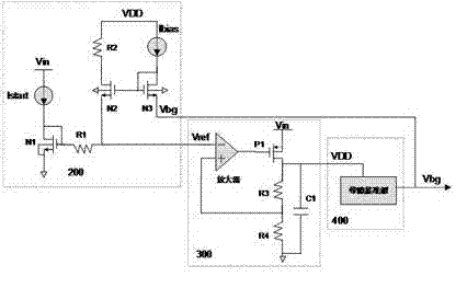
The invention discloses a start circuit which comprises a first NMOS (N-Mental-Oxide-Semiconductor) tube, a first resistor, a second resistor, a second NMOS tube and a third NMOS tube, wherein a grid electrode of the first NMOS tube is connected with a drain electrode and then is connected with a starting current source, and a source electrode of the first NMOS tube is earthed; one end of the first resistor is connected with the grid electrode of the first NMOS tube, and the other end of the first resistor is used as a bias voltage output end; a source electrode of the second NMOS tube is connected with bias voltage, and a drain electrode of the second NMOS tube is connected with the second resistor; a grid electrode of the third NMOS tube is connected with a drain electrode and then is connected with a bias current source, a grid electrode of the third NMOS tube is connected with that of the second NMOS tube, and a source electrode of the third NMOS tube is connected with constant voltage. The invention further discloses a voltage stabilizing circuit with the start circuit. According to the voltage stabilizing circuit, the bias voltage is used as reference input voltage of a linear regulator, power supply voltage is generated to supply power to a bandgap reference source, and bandgap reference voltage is generated by the bandgap reference source, so as to be used as reference and then be fed back to regulate the bias voltage in the start circuit, so that the accurate and stable power supply voltage can be obtained to be used for internal circuits in a chip.

Description

[0001] A starting circuit and a voltage stabilizing circuit with the starting circuit technical field [0002] The invention relates to the technical field of semiconductor circuits, in particular to a starting circuit and a voltage stabilizing circuit with the starting circuit. Background technique [0003] For semiconductor integrated circuits, in order to ensure the performance of the semiconductor chip, it is often required that its input voltage be stable. [0004] The input voltage Vin is often due to various reasons, such as input voltage jumps, input voltage is too high or there is interference in the input voltage, etc., making the input voltage unstable, so it is not suitable for directly supplying power to semiconductor chips, so as not to affect the performance of semiconductor chips. , and even damage the semiconductor chip. [0005] In order to solve the above problems, the existing method is to introduce a linear regulator to adjust the input voltage, and out...

Claims


Application Information

Patent Timeline
Patent Type & Authority Patents(China)
IPC IPC(8): G05F1/56
Inventor 张子秋
Owner SILLUMIN SEMICON CO LTD
Learn More