Amplifier circuit

a technology of amplifier circuit and amplifier, which is applied in the direction of amplifier, high-frequency amplifier, electrical apparatus, etc., can solve the problem of not being able to supply the detection signal from the emitter of the first transistor

Active Publication Date: 2019-06-20
DENSO TEN LTD
View PDF7 Cites 0 Cited by
  • Summary
  • Abstract
  • Description
  • Claims
  • Application Information

AI Technical Summary

Benefits of technology

[0010]According to the invention, it is possible to automatically control a gain of the external signal that is input to the first transistor.

Problems solved by technology

However, it is not preferable that the transformer is used for the amplifier circuit in terms of cost containment.
On the other hand, when the amplifier circuit is configured without using the transformer, since a level of an emitter signal of the first transistor decreases, it is not possible to supply the detection signal from the emitter of the first transistor.

Method used


Image

  • Amplifier circuit
  • Amplifier circuit
  • Amplifier circuit

Examples


Embodiment Construction

[0017]In the following, an embodiment of an amplifier circuit disclosed in the application will be described in detail with reference to the accompanying figures. The invention is not limited to the embodiment described in the following.

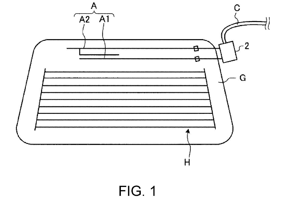
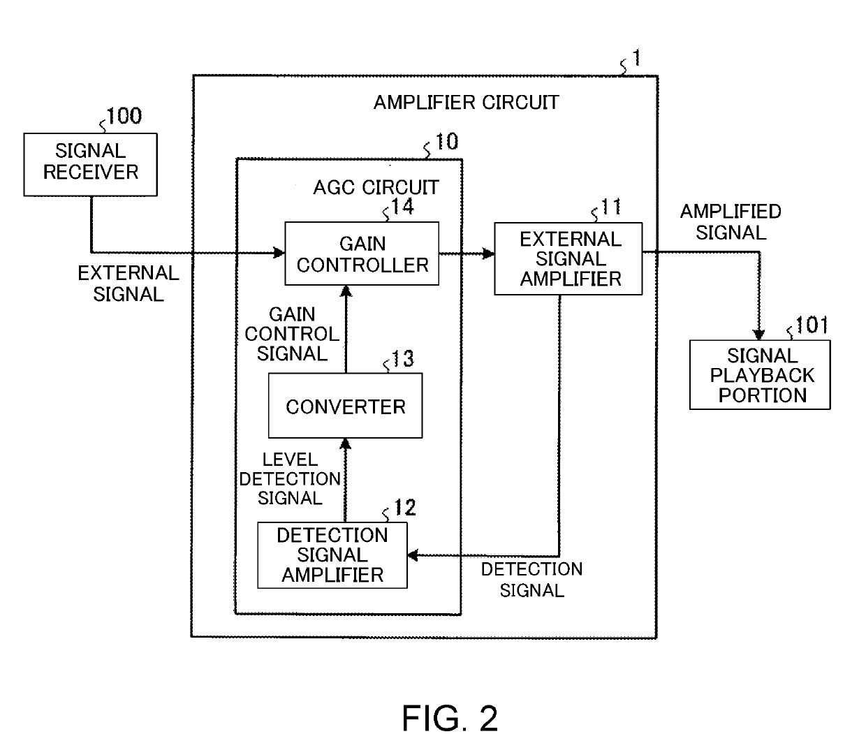
[0018]First, description will be made on configurations of an amplifier circuit 1 and an antenna amplifier 2 according to the embodiment with reference to FIG. 1 and FIG. 2. FIG. 1 is a diagram illustrating an outline of the antenna amplifier 2 according to the embodiment.

[0019]As illustrated in FIG. 1, a rear glass G of a vehicle is provided with an antenna A and a heater H. The antenna A includes a FM antenna A1 that mainly receives an FM broadcast radio wave, for example, in a frequency bandwidth of approximately 100 MHz and an AM antenna A2 that mainly receives an AM broadcast radio wave, for example, in a frequency bandwidth of approximately 1 MHz.

[0020]An external signal received by the antenna A is amplified by the antenna amplifier 2 that is ...


PUM


Abstract

An amplifier circuit includes a first transistor, a second transistor, a first pathway and a second pathway. The first transistor amplifies an external signal that is input from outside the amplifier circuit. The second transistor amplifies a detection signal that detects a level of the external signal. The first pathway is connected between a collector of the first transistor and a base of the second transistor to supply the detection signal that is output from the collector of the first transistor to the base of the second transistor. The second pathway is connected between an emitter of the first transistor and the base of the second transistor to supply a bias voltage from the emitter of the first transistor to the base of the second transistor.

Description

BACKGROUND OF THE INVENTIONField of the Invention[0001]The invention relates to an amplifier circuit.Description of the Background Art[0002]Conventionally, it has been known that an amplifier circuit that amplifies an external signal received by an antenna or the like is provided with an automatic gain control (AGC) circuit that automatically adjusts an amplifier gain according to a level of the external signal. In such an amplifier circuit, for example, negative feedback is applied from an emitter of a first transistor to a collector via a transformer (for example, refer to the patent document 1).[0003]FIG. 4 shows an amplifier circuit 1A that includes a conventional AGC circuit. The amplifier circuit 1A includes a first transistor Q11 and a second transistor Q12. The external signal that is transmitted from outside is input to a base of the first transistor Q11 of the amplifier circuit 1A. The external signal is amplified by the first transistor Q11 and such an amplified external ...

Claims


Application Information

Patent Timeline
Patent Type & Authority Applications(United States)
IPC IPC(8): H03F1/02H03F3/19
CPCH03F1/0211H03F3/19H03F2200/534H03F1/34H03F1/347H03F2200/541
Inventor OKANO, TETSUROKAWAI, KENJIHIRAI, MASAYOSHI
Owner DENSO TEN LTD
Why Eureka
Try Eureka