
Power type microswitch

A micro-switch, power-type technology, applied in electrical switches, snap-action devices, electrical components, etc., can solve problems such as arcing, and achieve the effects of large operating current, good impact resistance, and good vibration resistance.

Active Publication Date: 2013-12-11
中壹发展八五零电子有限公司
View PDF5 Cites 8 Cited by
  • Summary
  • Abstract
  • Description
  • Claims
  • Application Information

AI Technical Summary

Problems solved by technology

[0004] The purpose of the present invention is to provide a power type micro switch to solve or reduce the problem that the existing micro switch is prone to arcing during use, and to enhance the ability of the micro switch to resist arc burnout

Method used


Image

  • Power type microswitch
  • Power type microswitch
  • Power type microswitch

Examples


Embodiment Construction

[0023] The present invention will be further described below through specific embodiments.

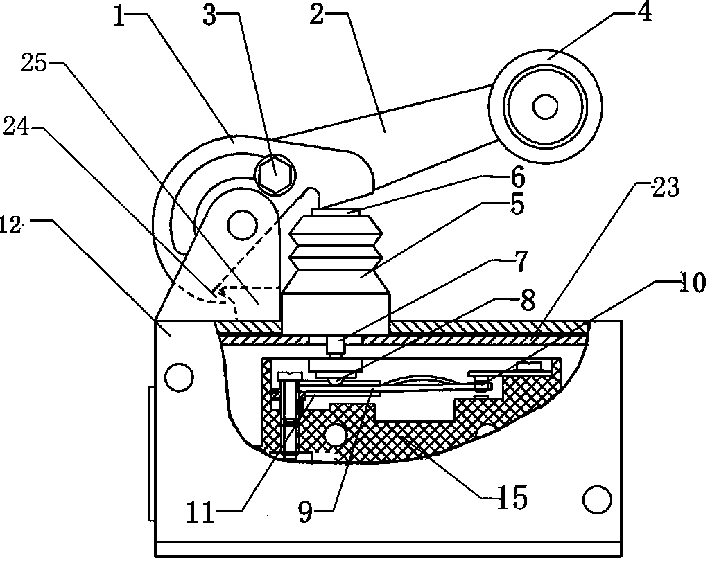
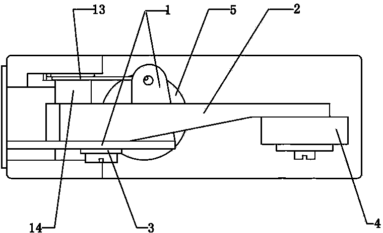
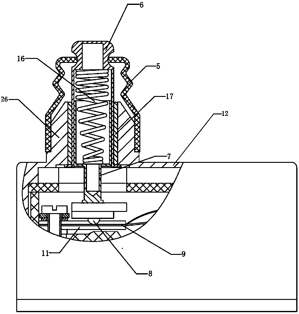
[0024] Such as figure 1 As shown, the present invention is provided with a double-layer protective shell (outer shell 12 and inner shell 23 ) made of metal materials, and a base 15 is arranged inside the protective shell, and the base 15 is made of phenolic plastic. The base 15 is provided with a contact reed assembly, the housing 12 is provided with a rolling touch assembly for controlling the switching action, and a button actuating assembly is provided between the contact reed assembly and the rolling touch assembly.

[0025] contact reed assembly (such as figure 1 As shown), it includes an upper reed with an upper static contact, a lower reed with a lower static contact, a movable reed 9 that drives a contact 10, and a spring positioning support piece 11. The upper reed and the lower reed are fixed on the base 15 respectively, so that the upper static contact is opposite to the l...


PUM


Abstract

The invention discloses a power type microswitch. The power type microswitch comprises a contact spring assembly, a rolling touch assembly and a button actuating assembly, wherein the contact spring assembly is arranged on a base, the rolling touch assembly is arranged on an outer shell, and the button actuating assembly is arranged between the contact spring assembly and the rolling touch assembly. The contact spring assembly comprises an upper spring leaf with an upper stationary contact, a lower spring leaf with a lower stationary contact, a movable spring leaf with a movable contact and a spring lifting locating and supporting chip. The rolling touch assembly comprises a folded edge touch plate with a circular arc adjusting groove, a rocking bar, a rolling wheel, a torsion spring and a limiting boss. The button actuating assembly comprises a button, a push rod, a touch button, a conical spring and a protecting bush. The power type microswitch has the advantages of being high in protection (dustproof, waterproof) level, good in environment resistance, small in movement clearance, large in working current and the like. The special structure of the button actuating assembly enables the microswitch to be straightforward in power connection when electrification switching is carried out, reduces and even avoids the phenomena such as contactor adhesion and arc discharge, prolongs the service life of the microswitch and improves the working reliability of the microswitch.

Description

technical field [0001] The invention relates to a micro switch, in particular to a power type micro switch. Background technique [0002] A micro switch is a switch with a small contact interval and a quick action mechanism, and a drive rod outside it, also called a sensitive switch. Micro switches are devices with relatively precise structure, so they are more prone to failure. At present, one of the main factors causing the failure of power micro switch is the generation of arc. Arc is when breaking or connecting a circuit with a voltage exceeding 10V and a current exceeding 100MA, a cloud of extremely high temperature, extremely bright and conductive gas will be generated in the contact gap (or arc gap). The high temperature generated by the arc will burn the contacts, and in severe cases, it will cause phase-to-phase short circuit, electrical explosion, and fire, endangering the safety of personnel and equipment. [0003] The generation of the arc involves many factor...

Claims


Application Information

Patent Timeline
Patent Type & Authority Applications(China)
IPC IPC(8): H01H9/30H01H5/06
Inventor 韩金凤赵绪怀张莉崔艳梅丁乡王云香
Owner 中壹发展八五零电子有限公司
Learn More