Direct current breaking device and control method

A breaking device and circuit breaker technology, applied in the direction of overcurrent protection, etc., can solve the problems of unfavorable auxiliary circuit breaker isolation maintenance, failure to guarantee success, low breaking voltage, etc., to improve the use performance and the convenience of maintenance , Conducive to isolated maintenance, to ensure the effect of safety

Active Publication Date: 2013-12-11
NR ELECTRIC CO LTD +1
View PDF4 Cites 6 Cited by
  • Summary
  • Abstract
  • Description
  • Claims
  • Application Information

AI Technical Summary

Problems solved by technology

The auxiliary circuit breaker in this device itself has only a few power semiconductor devices connected in series, can only bear a low breaking voltage, and is easy to be damaged due to overvoltage. A group of high-speed mechanical switches are used in the prior art, which can bear relatively High breaking voltage, but the breaking of the high-speed mechanical switch does not guarantee success, there is a certain failure rate, and one end of the auxiliary circuit breaker uses a high-speed mechanical switch, and the other end is directly connected to the high-voltage line, there are also certain hidden dangers. It is also not conducive to the isolation and maintenance of auxiliary circuit breakers

Method used


Image

  • Direct current breaking device and control method

Examples


Embodiment Construction

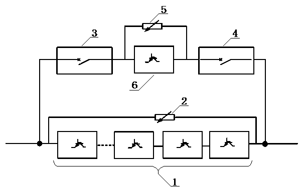
[0022] The specific implementation manners of the present invention will be further described in detail below in conjunction with the accompanying drawings.

[0023] Such as figure 1 As shown, the present invention designs a DC breaking device, including a main circuit breaker 1, an auxiliary circuit breaker 6, a first non-linear resistor 2 and a first high-speed mechanical switch 3, wherein the main circuit breaker 1 and the auxiliary circuit breaker 6 are respectively Including at least one power semiconductor switching device, each power semiconductor switching device is connected in series, and the number of power semiconductor switching devices in the main circuit breaker 1 is greater than the number of power semiconductor switching devices in the auxiliary circuit breaker 6, the first non-linear resistor 2 and the main circuit breaker The switches 1 are connected in parallel with each other, and the first high-speed mechanical switch 3 and the auxiliary circuit breaker 6...


PUM


Abstract

The invention relates to a direct current breaking device which comprises a main circuit breaker, an auxiliary circuit breaker, a first nonlinear resistor, a first high-speed mechanical switch and a second high-speed mechanical switch. The main circuit breaker and the auxiliary circuit breaker respectively comprise at least one power semiconductor switching device. The power semiconductor switching devices are mutually connected in series, and the number of the power semiconductor switching devices in the main circuit breaker is larger than the number of the power semiconductor switching devices in the auxiliary circuit breaker. The first nonlinear resistor and the main circuit breaker are mutually connected in parallel, the first high-speed mechanical switch and the second high-speed mechanical switch are connected with the two ends of the auxiliary circuit breaker respectively in series to form an on-state branch circuit, and the on-state branch circuit and the main circuit breaker are connected in parallel. The invention further relates to a control method based on the direct current breaking device, and comprehensive protection can be effectively provided for the working process of the auxiliary circuit breaker.

Description

technical field [0001] The invention relates to a DC breaking device and a control method. Background technique [0002] In the multi-terminal HVDC power transmission system, the DC breaker is one of the most important devices. Due to the high voltage level and small line impedance of the multi-terminal HVDC transmission system, once a line short-circuit fault occurs, it will quickly affect the DC transmission network and the AC network, and the fault must be removed quickly. Therefore, the DC breaker needs to operate quickly, which can minimize the fault duration or suppress the fault current, and reduce the impact of the fault on the AC / DC transmission network. [0003] In the prior art, a hybrid DC breaking device is composed of a main circuit breaker, a high-speed mechanical switch, an auxiliary circuit breaker and a non-linear resistor energy-consuming element. The auxiliary circuit breaker in this device has only a small number of power semiconductor devices connec...

Claims


Application Information

Patent Timeline
IPC IPC(8): H02H3/08
Inventor 杨浩曹冬明王宇杨兵石巍吕玮刘为群方太勋
Owner NR ELECTRIC CO LTD
Why Eureka
Try Eureka