Longitudinal-transverse-vertical force cooperative control method of distributed electrically driven vehicle

A technology of collaborative control and vehicle control system, which is applied in the field of optimal distribution and control of longitudinal and vertical forces of horizontal and distributed electric drive vehicles, and can solve problems such as inability to achieve control effects, lack of theoretical basis, unified optimal distribution, etc.

Active Publication Date: 2013-12-18
TSINGHUA UNIV
View PDF5 Cites 41 Cited by
  • Summary
  • Abstract
  • Description
  • Claims
  • Application Information

AI Technical Summary

Problems solved by technology

In existing studies, most of the active suspension forces are used to control the vehicle body’s vertical vibration, pitch, roll and other vehicle body attitude targets; for the handling stability target, only the minimum dynamic load of the tire or the proportional follow-up of the braking torque are considered, and it is not based on the actual vehicle Comprehensive optimization design of the vertical force of each wheel
Secondly, the existing chassis integrated control system has not yet proposed a method that can truly realize the uniform and optimal distribution of tire longitudinal, lateral and vertical forces
The current research can only realize the uniform and optimized distribution of tire longitudinal and lateral forces, while the distribution of tire vertical forces mostly adopts artificial decoupling methods such as dividing empirical working conditions and equal distribution, which lacks rigorous theoretical basis and cannot achieve optimal Control effect

Method used


Image

  • Longitudinal-transverse-vertical force cooperative control method of distributed electrically driven vehicle
  • Longitudinal-transverse-vertical force cooperative control method of distributed electrically driven vehicle
  • Longitudinal-transverse-vertical force cooperative control method of distributed electrically driven vehicle

Examples


Embodiment Construction

[0080] The present invention will be described in detail below in conjunction with the accompanying drawings and embodiments.

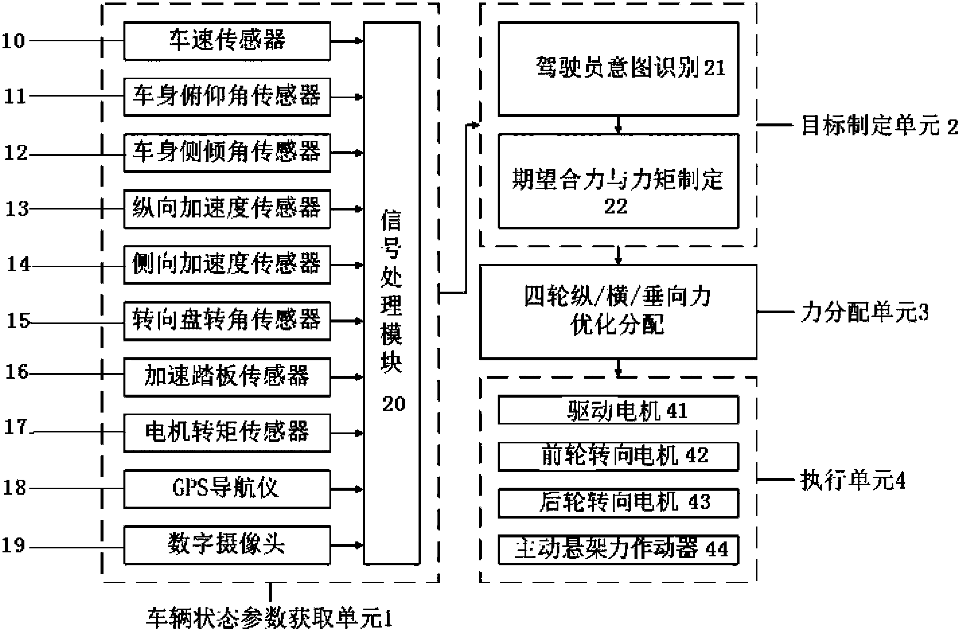
[0081] Such as figure 1 As shown, in order to realize the cooperative control method of longitudinal, horizontal and vertical forces described in the present invention, the present invention provides a chassis integrated control system, based on which the collection of parameters, the formulation and distribution of forces, and the final implement. Therefore, the control system is mainly composed of vehicle state parameter acquisition unit 1 , target formulation unit 2 , force distribution unit 3 and execution unit 4 . Among them, the vehicle state parameter acquisition unit 1 obtains the state parameters required by the system through sensors; the target formulation unit 2 judges the driver's intention according to the vehicle state information obtained by the vehicle state parameter acquisition unit 1 and uniformly formulates the vehicle's longitud...


PUM


Abstract

The invention relates to a longitudinal-transverse-vertical force cooperative control method of a distributed electrically driven vehicle. The method is implemented by a vehicle control system: 1) formulation of expected resultant force and moment; 2) optimal distribution of longitudinal, transverse and vertical forces of four wheels; 3) specific execution of the forces. The expected values of the resultant force and the moment of the whole vehicle are obtained by utilizing various information of the vehicle, an integrated tyre force optimization problem is formed by establishing a constraint condition and an objective function, and an optimization solution algorithm is designed for the problem, wherein the optimization algorithm comprises a constraint optimization method which adopts a barrier function method and a Newton method, and a feasible region planning method based on vehicle state continuity. The method does not need to implement different control strategies according to different work conditions of tyres, realizes unified optimal distribution and control of the longitudinal, transverse and vertical forces of the tyres, comprehensively improves the operation stability and the driving posture of the vehicle, and can be applied to driverless operation of vehicles in the future.

Description

technical field [0001] The invention relates to an integrated chassis control technology of a distributed electric drive vehicle, in particular to a method for optimal distribution and control of longitudinal, horizontal and vertical forces of a distributed electric drive vehicle. Background technique [0002] With the advancement and development of automobile technology, various chassis electronic control technologies have been widely studied and applied. These chassis electronic control technologies mainly carry out active control from the three aspects of tire longitudinal, lateral and vertical forces, respectively, to improve vehicle handling stability or improve vehicle driving posture. However, due to the complex characteristics of severe coupling of dynamics in the vehicle system, there are conflicts or complementarities in various degrees in the control objectives and execution effects of various chassis electronic control systems. In order to eliminate conflicts be...

Claims


Application Information

Patent Timeline
Patent Type & Authority Applications(China)
IPC IPC(8): B60W30/02
Inventor 罗禹贡曹坤李克强褚文博戴一凡连小珉杨殿阁王建强郑四发
Owner TSINGHUA UNIV
Why Eureka
Try Eureka