Electromagnetic pressure relief valve

A pressure relief valve and electromagnetic technology, applied in the field of solenoid valves, can solve the problems of increasing the overall cost of the electromagnetic pressure relief valve 100 and the inability to reduce the manufacturing cost, and achieve the effects of reducing the manufacturing time, reducing the manufacturing cost, and improving the pressure relief efficiency.

Active Publication Date: 2013-12-18
XIAMEN KOGE MICRO TECH
View PDF8 Cites 2 Cited by
  • Summary
  • Abstract
  • Description
  • Claims
  • Application Information

AI Technical Summary

Problems solved by technology

In order to allow the opening of the air inlet hole 114a to be easily sealed by the anti-leak gasket 106, more precise processing is required near the opening of the air inlet hole 114a, so that the manufacturing cost of the integrated metal parts of the air nozzle 120 and the magnet collector 114 cannot be reduced. The overall cost of the associated electromagnetic pressure relief valve 100 also increases accordingly

Method used


Image

  • Electromagnetic pressure relief valve
  • Electromagnetic pressure relief valve
  • Electromagnetic pressure relief valve

Examples


Embodiment Construction

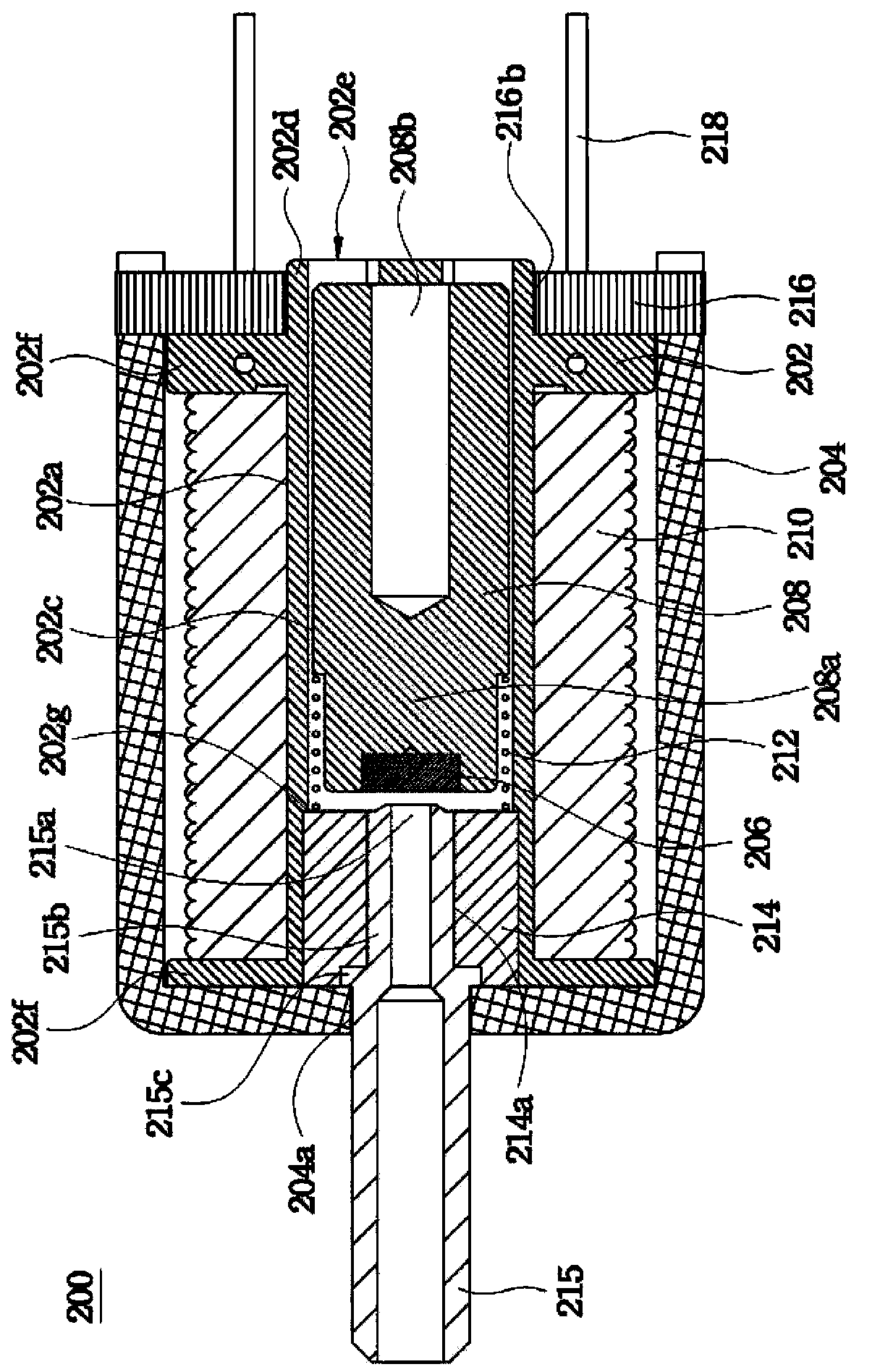
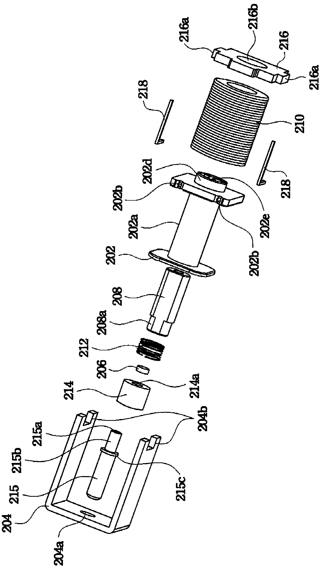
[0031] Please also refer to figure 2 , 3 , figure 2 is a sectional view illustrating an electromagnetic pressure relief valve according to an embodiment of the present invention, image 3 is to draw figure 2 Exploded view of the solenoid pressure relief valve. The electromagnetic pressure relief valve 200 basically consists of an outer frame 204 , a magnet collector 214 , a plastic valve 215 , a coil module, a movable inner core 208 and a spring 212 . The plastic valve 215 is used to connect to a pipeline that needs to be released for pressure relief, and the pipeline that needs to be released can be any fluid pipeline. Under normal conditions, the electromagnetic pressure relief valve 200 utilizes the elastic force of the spring 212 to prevent the air inlet 215a from being blocked or sealed by the anti-leakage gasket 206, and flows through the hollow groove 202c to the pressure relief hole 202e to release the pressure, so that the pipe that needs pressure relief The r...


PUM


Abstract

An electromagnetic pressure relief valve comprises an outer frame, an integrated magnet, a plastic air tap, a coil module, a movable inner core and a spring. The outer frame is provided with a through hole. The integrated magnet is provided with a hollow channel. One end of the plastic air tap penetrates the through hole and is exposed outside, the other end thereof penetrates the channel, and an air inlet of the plastic air tap is exposed. The coil module is fixed in the outer frame and provided with a hollow groove which is sleeved outside the integrated magnet. The movable inner core is arranged in the hollow groove in a slidable mode, and one end portion of the movable inner core is provided with a leakage-stop spacer used for sealing the air inlet. The spring is connected between the plastic air tap and the movable inner core, and enables the leakage-stop spacer to be away from the air inlet through elastic force. When the coil module is powered on to perform excitation, the integrated magnet and the movable inner core are mutually attracted to resist the elastic force of the spring so as to enable the leakage-stop spacer to seal the air inlet.

Description

【Technical field】 [0001] The present invention relates to a solenoid valve, and in particular to a solenoid pressure relief valve. 【Background technique】 [0002] Please refer to figure 1 , which shows a cross-sectional view of an electromagnetic pressure relief valve in the prior art. The air nozzle 120 of the electromagnetic pressure relief valve 100 can be connected to a pipeline that needs pressure relief. When the electromagnetic pressure relief valve 100 is in a normal state, the anti-leakage gasket 106 utilizes the elastic force of the spring 112 to prevent the air inlet 114a from being blocked or sealed, so that the pipeline that needs to be relieved maintains the action of pressure relief. When the pipeline does not need to release pressure, the coil 110 in the electromagnetic pressure relief valve 100 is energized and excited, so that the collector 114 attracts the movable inner core 108 and resists the elastic force of the spring 112, and pushes the anti-leakage...

Claims


Application Information

Patent Timeline
Patent Type & Authority Applications(China)
IPC IPC(8): F16K1/00F16K31/06
CPCF16K1/00F16K31/0655F16K31/0675
Inventor 董振凯杨胜闵
Owner XIAMEN KOGE MICRO TECH
Why Eureka
Try Eureka