Hydraulic brake valve of feedback piston of valve core

A hydraulic brake valve and valve core technology, applied in valve devices, safety valves, multi-way valves, etc., can solve the problems of increasing the compression amount, increasing the stroke of the push rod, large rigidity, etc., and achieves low braking control force and structure. The effect of simplicity and reduced manipulation force

Inactive Publication Date: 2013-12-18
JIMEI UNIV
View PDF6 Cites 4 Cited by
  • Summary
  • Abstract
  • Description
  • Claims
  • Application Information

AI Technical Summary

Problems solved by technology

In addition, due to the large balance force, the balance spring requires greater stiffness or increased compression. The large stiffness

Method used


Image

  • Hydraulic brake valve of feedback piston of valve core
  • Hydraulic brake valve of feedback piston of valve core
  • Hydraulic brake valve of feedback piston of valve core

Examples


Embodiment Construction

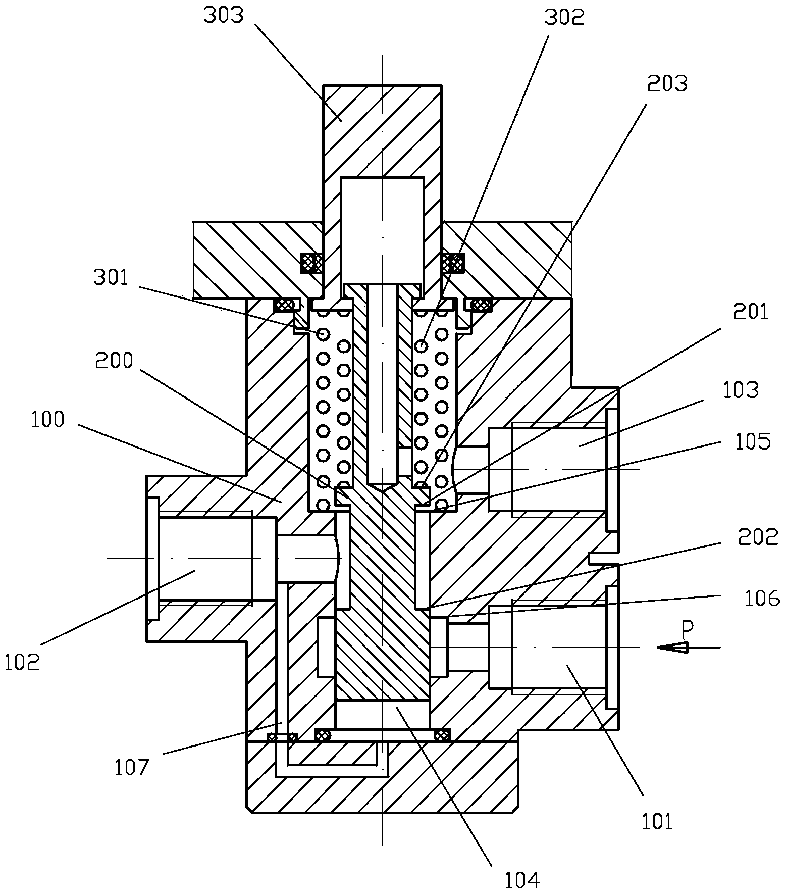
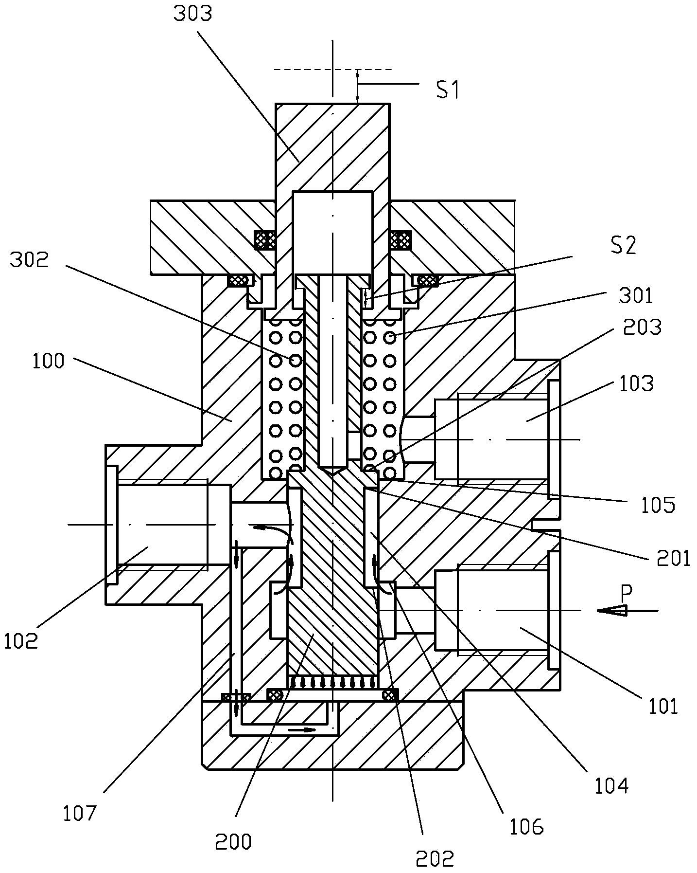
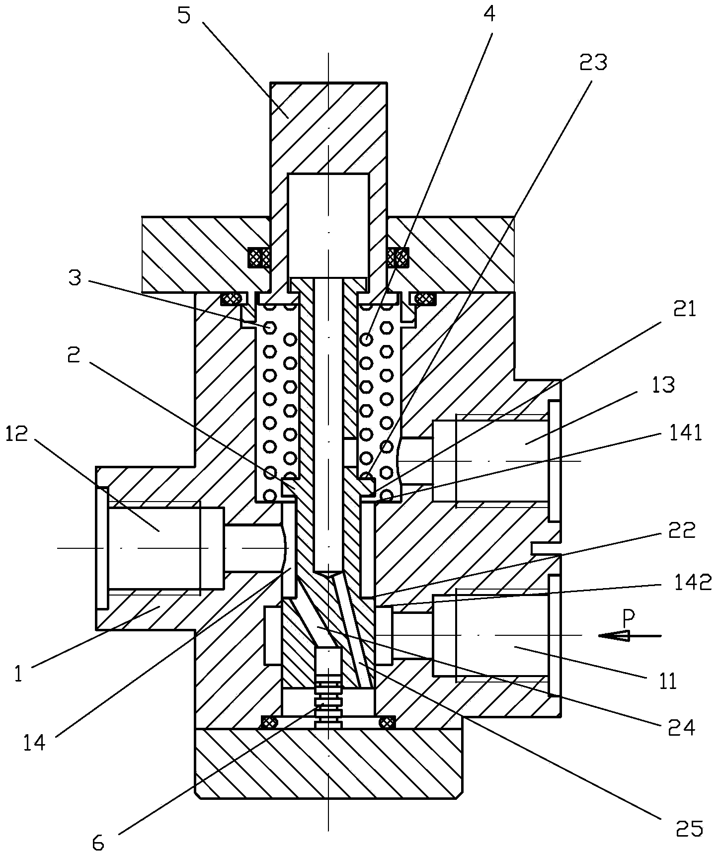
[0015] Examples, see Figure 3 to Figure 4 As shown, the spool feedback piston hydraulic brake valve of the present invention includes a valve body 1, a spool 2, a return spring 3, a balance spring 4, and a push rod 5. The valve body 1 has an input port 11 and an output port 12. The oil return port 13 and the valve core cavity 14, the input port 11, the output port 12, and the oil return port 13 are respectively communicated through the valve core cavity 14. The valve core 2 is slidingly connected in the valve core cavity 14, and the push rod 5 It is movably connected to the upper end of the valve core 2; the valve core cavity 14 is respectively provided with a first annular groove edge 141 and a second annular groove edge 142, and the valve core 2 is respectively provided with a first shoulder 21 and a second shoulder 22 and the third shoulder 23, the balance spring 4 is elastically stretched between the bottom end of the push rod 5 and the third shoulder 23 of the valve core,...


PUM


Abstract

The invention discloses a hydraulic brake valve of a feedback piston of a valve core. The hydraulic brake valve comprises a valve body, the valve core, a return spring, a balance spring and a push rod, wherein the valve body is provided with an input port, an output port, an oil return port and a valve core cavity, the input port, the output port and the oil return port are respectively communicated through the valve core cavity, the valve core is connected to the valve core cavity in a sliding manner, and the push rod is movably connected to the upper end of the valve core; a feedback passage is arranged in the valve core, and the feedback channel is communicated between the output port of the valve body and the bottom end of the valve core cavity; the hydraulic brake valve further comprises the feedback piston, wherein the upper part of the feedback piston is contained in the feedback passage, and the bottom end face of the feedback piston is in contact with the bottom surface of the valve core cavity. According to the invention, through redesigning the structure of the feedback passage and adding the feedback piston, the hydraulic brake valve has the characteristics of high flow, low control force, stable output pressure and controllable size.

Description

Technical field [0001] The invention relates to a brake valve, in particular to a spool feedback piston hydraulic brake valve. Background technique [0002] In the hydraulic system, due to the requirements of actual working conditions, the liquid output pressure needs to be stable and the size can be controlled. For example, the hydraulic braking system and hydraulic clamping system of mobile construction machinery need to control the stability and magnitude of the braking force or clamping force, and the magnitude of the output force is determined by the pressure of the liquid, so in these systems The hydraulic pressure reducing valve which can control the size and stable output of the liquid pressure is widely used. However, many of these hydraulic systems require a large flow output while controlling the pressure. This requires increasing the diameter of the spool, and increasing the diameter of the spool will increase the feedback area, and the increase in the feedback force...

Claims


Application Information

Patent Timeline
IPC IPC(8): F16K11/07F16K17/30
Inventor 皮钧凌西亮
Owner JIMEI UNIV
Why Eureka
Try Eureka