Heating device for pipeline

A heating device and pipeline technology, which is applied in the direction of pipeline heating/cooling, heating element shape, pipe/pipe joint/pipe fitting, etc., can solve the problems of affecting heating efficiency, heating device is not tightly bonded, etc., to increase heating efficiency, heating Visible, intensity-increasing effects

Inactive Publication Date: 2013-12-18
扬中市金元化工电力设备厂
View PDF9 Cites 6 Cited by
  • Summary
  • Abstract
  • Description
  • Claims
  • Application Information

AI Technical Summary

Problems solved by technology

However, due to the uneven diameter of the pipes, the heating device

Method used


Image

  • Heating device for pipeline
  • Heating device for pipeline
  • Heating device for pipeline

Examples


Embodiment Construction

[0021] The present invention will be further described below in conjunction with accompanying drawing.

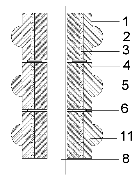
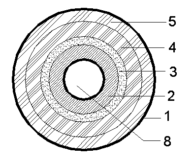
[0022] As shown in the figure, a heating device for pipelines includes a casing 1, in which a heating layer 2, an insulating layer 3 and a thermal insulation layer 4 are sequentially arranged, and the casing 1 is a split structure, consisting of two semicircular casings 11, connected into one body by fasteners, covering the outer wall of the pipe 8, wherein, the outer periphery of the semicircular shell 11 is provided with arc-shaped protrusions 5, and the two ends of the protrusions 5 are provided with hinges The connecting device 6 is connected by a hinge between the upper and lower semicircular shells 11;

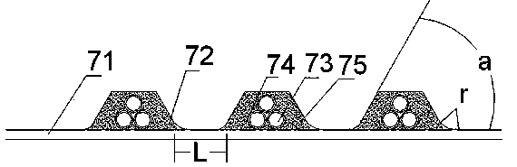
[0023] The heating layer 2 is formed by the cooperation of two electric heating belts 7, the electric heating belt 7 includes a housing 71, and the housing 71 is a belt-shaped structure, wherein the housing 71 is a A plurality of protrusions 72 are provided on the si...


PUM


Abstract

The invention relates to a heating device for a pipeline, which comprises an outer casing, wherein heating layers, insulating layers and heat preservation layers are arranged inside the outer casing in sequence; the outer casing adopts a split type structure, and is encircled by two semi-circular outer casings connected into a whole through a fastener; circular arc bulges are arranged on the periphery of each semi-circular outer casing; hinge connecting devices are arranged at the two ends of each bulge; the two upper and lower semi-circular outer casings are connected through a hinge. Therefore, the heating device is more fitted with the pipeline, and the heating efficiency is higher.

Description

technical field [0001] The invention relates to an electric heating device for pipelines, belonging to the technical field of electric heaters. Background technique [0002] In recent years, electric heating plates using nickel-chromium alloy sheets for electric heaters have been produced, which have high thermal efficiency, small thermal inertia, and fast temperature rise. However, its stability is poor under high temperature conditions, and its flat plate structure is not easy to fit with various shapes of elements to be heated, and it is prone to deformation and fracture, which affects work efficiency. [0003] The company's existing heating device for pipelines includes a shell, and the shell is provided with a heating layer, an insulating layer and a thermal insulation layer in turn. The shell is surrounded by two semicircular shells and connected by fasteners One. However, due to the unequal diameter of the pipes, the heating device is not tightly fitted, which ultim...

Claims


Application Information

Patent Timeline
IPC IPC(8): F16L53/00H05B3/44
Inventor 朱红保
Owner 扬中市金元化工电力设备厂
Why Eureka
Try Eureka