Heat transfer bridge sensor for measuring scour and silt depth around steel pipe piles of bridges

A technology of bridge-type sensors and steel pipe piles, which is applied in the direction of measuring devices and instruments, can solve problems such as the inability to realize automatic monitoring, unfavorable large-scale promotion of technologies, and complicated sensor installation, and achieve simple and reliable measurement principles, good economic benefits, The effect of broad application prospects

Inactive Publication Date: 2015-12-02
湖北鑫晨光建设工程有限公司
View PDF7 Cites 0 Cited by
  • Summary
  • Abstract
  • Description
  • Claims
  • Application Information

AI Technical Summary

Problems solved by technology

[0002] As a form of bridge foundation, steel pipe piles have been widely used in the construction of various types of bridges. However, the monitoring of scour and silt depth around steel pipe piles of bridges is still at a stage with a very low level of automation, such as water level gauges. Unable to realize round-the-clock automatic monitoring
Although some new scouring and sedimentation sensors provide the possibility of automatic monitoring, the installation of the sensors is complicated, which is not conducive to the large-scale promotion of the technology

Method used


Image

  • Heat transfer bridge sensor for measuring scour and silt depth around steel pipe piles of bridges
  • Heat transfer bridge sensor for measuring scour and silt depth around steel pipe piles of bridges
  • Heat transfer bridge sensor for measuring scour and silt depth around steel pipe piles of bridges

Examples


Embodiment Construction

[0026] The present invention will be further described in detail below in conjunction with the accompanying drawings.

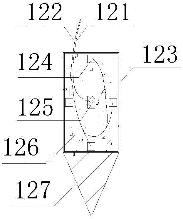
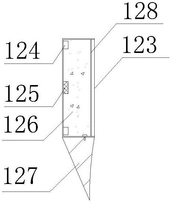
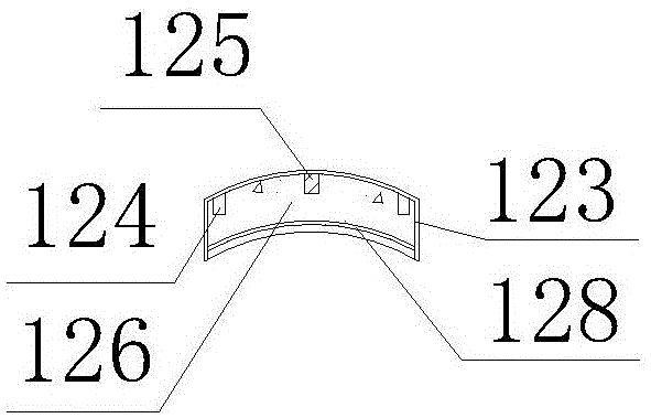
[0027] Combining Figure 1 and figure 2 , The sensor 12 includes a power line 121 , a signal line 122 , a housing 123 , a temperature probe 124 , a heating block 125 , a heat insulating material 126 , a cone 127 , and a sealing plate 128 . The housing 123 is welded by stainless steel sheets with tile-shaped side walls and semicircular ends. The pointed cone 127 is half a solid cone, and the top surface of the pointed cone 127 is connected to the bottom surface of the housing 123 by bolts. The center of the inner side wall of the casing 123 is a heating block 125, and a temperature probe 124 is located at the midpoint of each of the four sides. The power line 121 of the heating block 125 and the signal line 122 of the temperature probe 124 are drawn out from the top of the casing 123 . The rest of the space in the casing 123 is filled with a heat insulating ...


PUM


Abstract

The invention discloses a heat transmission bridge type sensor for measuring erosion and deposition depth on the periphery of a bridge steel pipe pile. The heat transmission bridge type sensor for measuring the erosion and deposition depth on the periphery of the bridge steel pipe pile is based on the principle that a heat source and temperature sensing points are located at the two ends of a heat transmission bridge respectively, the heat emitted by the heat source is transmitted to the temperature sensing points through the heat transmission bridge, and when the heat transmission bridge is located in a water body, the heat loss is in positive correlation with the water velocity and is larger than that in a soil body obviously. The heat transmission bridge type sensor for measuring the erosion and deposition depth on the periphery of the bridge steel pipe pile comprises a shell body, a heat emitting block, temperature probes and other components. The heat emitting block is arranged in the center of the side wall of the inner side of the shell body, and the temperature probes are arranged on the middle points of the four edges of the shell body respectively. The heat emitting block is served as the heat source, and the shell body is served as the heat transmission bridge and transmits heat to the temperature sensors (the temperature sensing points). Rated currents are input to enable the heating block to emit heat continuously, and whether the environment where the sensor located is the water body or the soil body can be distinguished simply by measuring the temperature changing speed and the temperature changing range of the temperature probes in the heating process. A plurality of sensors are arranged at the positions of different depths on the pile body of the steel pipe pile, the boundary surface of the water body and the soil body can be distinguished, and the erosion and deposition depth on the periphery of the bridge steel pipe pile can be determined finally.

Description

technical field [0001] The invention relates to a water conservancy project monitoring device, in particular to a heat transfer bridge sensor for measuring the scouring and silting depth around steel pipe piles of bridges. Background technique [0002] As a form of bridge foundation, steel pipe piles have been widely used in the construction of various types of bridges. However, the monitoring of scour and silt depth around steel pipe piles of bridges is still at a stage with a very low level of automation, such as water level gauges. All-weather automatic monitoring cannot be realized. Although some new scouring and sedimentation sensors provide the possibility of automatic monitoring, the installation of the sensors is complicated, which is not conducive to the large-scale promotion of the technology. [0003] The rate of heat loss is closely related to the environment. The water environment is easier to dissipate heat than the soil environment, and the heat dissipation r...

Claims


Application Information

Patent Timeline
Patent Type & Authority Patents(China)
IPC IPC(8): G01B21/18
Inventor 丁勇
Owner 湖北鑫晨光建设工程有限公司
Why Eureka
Try Eureka