
Vibrating washout sensor

A vibration sensing and sensor technology, which is applied in the field of water conservancy engineering monitoring devices, can solve the problems of difficult real-time and accurate monitoring of pile foundation and embankment scouring status, potential safety hazards of structures, and many interference factors, and achieve simple, reliable and good measurement principles. The effect of economic benefit and simple production process

Inactive Publication Date: 2016-01-20
NANJING UNIV OF SCI & TECH
View PDF5 Cites 0 Cited by
  • Summary
  • Abstract
  • Description
  • Claims
  • Application Information

AI Technical Summary

Problems solved by technology

These large structures will change the surrounding wave and water flow conditions, and the resulting erosion will gradually reduce the strength of the foundation of the structure, causing hidden dangers to the safety of the structure and endangering the property and life safety of the general public
[0003] The current scour monitoring methods mainly include artificial depth gauge, sonar, radar and time domain reflectometer (TDR), etc., but these methods have great limitations in practical engineering applications, such as offline, low precision, poor stability, cost, etc. It is difficult to monitor the scour status of pile foundation and embankment in real time and accurately
[0004] There are some new scour sensors, such as "Fiber Bragg Grating Scour Monitoring Sensor and Its Manufacturing Method" with patent No. 200710144304.5, "A High Durability Fiber Bragg Grating Scour Sensor" with patent No. 200710144305.X, and 201110352894.7 with patent "Long Gauge Fiber Bragg Grating Scouring Sensor and Its Fabrication, Installation and Layout Method, and Scouring Monitoring System Consisting of It", they use optical fiber gratings and other sensing elements to realize dynamic real-time scour monitoring, which is more accurate than traditional monitoring methods Accurate; but the manufacturing process of these sensors is complicated, the measurement variable is determined according to the signal strength value of the sensing element, there are many interference factors, the cost is high, and it cannot meet the actual needs of the scouring monitoring environment in our country

Method used


Image

  • Vibrating washout sensor
  • Vibrating washout sensor
  • Vibrating washout sensor

Examples


Embodiment Construction

[0030] The present invention will be described in further detail below in conjunction with the accompanying drawings.

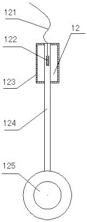
[0031] combine figure 1 , Vibration scour sensor, 1 includes a fixed frame 11 and a vibration sensing probe 12, and a vibration sensing probe 12 is arranged on the inside of the top of each layer of the fixed frame 11.

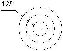
[0032] combine figure 2 As shown in FIG. 3 , the vibration sensing probe 12 includes a signal line 121 , a strain sensing element 122 , a protective case 123 , a conductive rod 124 , and a wave plate 125 . One end of the conductive rod 124 is connected to the edge of the wave plate 125, and the other end is pasted with the strain sensing element 122 and the signal line is drawn out. The protective shell 123 is a half metal cylinder with a bayonet opening at the center of the bottom surface. Two identical protective shells 123 are press-fitted to cover the strain sensing element 122 at the top of the conduction rod, and the remaining bayone...


PUM


Abstract

The invention discloses a vibrating scouring sensor. The vibrating scouring sensor comprises a fixed bracket and vibrating sensing probes, wherein the top inner side of each layer of the fixed bracket is respectively provided with one vibrating sensing probe. When the vibrating sensing probe is arranged in the water, a stress sensing element in the vibrating sensing probe can be driven by the water stream variation to have vibrating deformation, and whether the probe is placed in the water or not can be judged according to the vibration amplitude and the vibration frequency of the measured stress data; if the vibrating sensing probe is arranged in the soil, the soil is relatively stable, and the stress data obtained by the sensing probe is hardly changed; and the depth of a mud surface can be determined by distinguishing the water and the soil according to the vibration amplitude and the vibration frequency of the stress data. The vibrating scouring sensor is not subject to the interference of factors such as the variation of temperature, has the advantages of no temperature drift and no null drift, is simple to produce and low in cost and can change the measurement precision and the measurement depth range according to the application condition and requirement. When the vibrating sensing sensor is installed in multiple monitoring places, the regional scouring monitoring can be realized.

Description

technical field [0001] The invention relates to a water conservancy project monitoring device, in particular to a vibrating scour sensor. Background technique [0002] In recent years, with the continuous development and utilization of marine resources in China, a large number of marine engineering structures have appeared in my country's coastal areas, such as coastal protection projects, cross-sea bridges and large ports. These large structures will change the surrounding wave and water flow conditions, and the resulting erosion will gradually reduce the strength of the foundation of the structure, causing hidden dangers to the safety of the structure, and endangering the property and life safety of the general public. [0003] The current scour monitoring methods mainly include artificial depth gauge, sonar, radar and time domain reflectometer (TDR), etc., but these methods have great limitations in practical engineering applications, such as offline, low precision, poor ...

Claims


Application Information

Patent Timeline
Patent Type & Authority Patents(China)
IPC IPC(8): G01M7/02
Inventor 丁勇方海东何宁崔何亮姚庆雄左晓宝
Owner NANJING UNIV OF SCI & TECH
Learn More