Oil level control switch of oil cooling tank

A technology of liquid level control and cooling box, applied in the direction of electrical switches, electrical components, circuits, etc., can solve the problems of mechanical failure, oil overflow, delay of switch control timing, etc., to achieve the effect of improving the safety of use

Inactive Publication Date: 2013-12-18
乳山市黄海汽车配件有限公司
View PDF0 Cites 3 Cited by
  • Summary
  • Abstract
  • Description
  • Claims
  • Application Information

AI Technical Summary

Problems solved by technology

[0002] We know that in the hydraulic control system, when the viscosity of the oil in the cooling tank is too high or the flow speed of the oil is too fast, the operator cannot judge in time, delaying the control timing of the switch, causing oil overflow and affecting the worker's safety. In the production environment, in serious cases, it will cause mechanical failure, which delays the working hours and disperses the labor energy of the workers.

Method used


Image

  • Oil level control switch of oil cooling tank

Examples


Embodiment Construction

[0008] The present invention will be further described below in conjunction with accompanying drawing:

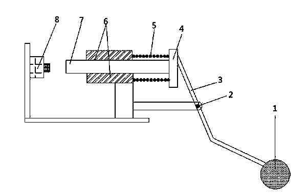
[0009] Such as figure 1 As shown, the present invention relates to a liquid level control switch of an oil cooling tank, which is provided with a float 1, a lever 3, a pin shaft 2, a piston 4, a spring 5, a slider 6, a fixed shaft 7, and a switch 8. The floating ball 1 is located at the lower end of the lever 3, the lower end of the floating ball 1 is oil, the middle part of the lever 3 is fixed by the pin shaft 2, the upper end of the lever 3 is connected with the piston 4, the piston 4 is connected with the slider 6 through the spring 5, and the piston 4 and the slider Block 6 is all installed on the fixed shaft 7, and the left side of fixed shaft 7 is provided with switch 8.

[0010] When the present invention is used, when the oil level rises, the floating ball also rises with the liquid level, the lever rotates counterclockwise around the pin shaft, and the upper end ...


PUM


Abstract

The invention relates to an oil level control switch of an oil cooling tank. The oil level control switch comprises a float ball, a lever, a pin, a piston, a spring, a slider, a fixed shaft, a switch and the like. The oil level control switch is characterized in that the float ball is located at the lower end of the lever and the lower end of the float ball touches oil; the middle of the lever is fixed by the pin, the lever is capable of rotating around the pin and the upper end of the lever is connected with the piston; the piston is connected with the slider through the spring, both the piston and the slider are mounted on the fixed shaft and capable of reciprocating along the axial direction of the fixed shaft; the switch is arranged on the left of the fixed shaft, and the slider can touch the switch when moving leftwards, so that start and stop states of a circulating pump are controlled. With the oil level control switch, oil spilling is avoided thoroughly and safety in use of equipment is improved.

Description

technical field [0001] The invention relates to a control switch, in particular to a liquid level control switch of an oil cooling tank. Background technique [0002] We know that in the hydraulic control system, when the viscosity of the oil in the cooling tank is too high or the flow speed of the oil is too fast, the operator cannot judge in time, delaying the control timing of the switch, causing oil overflow and affecting the worker's safety. The production environment, in serious cases, will cause mechanical failures, which delays working hours and disperses the labor energy of workers. Contents of the invention [0003] The technical problem to be solved by the present invention is to overcome the deficiencies of the above-mentioned prior art, and provide an automatic control, time-saving and labor-saving, and high operational safety oil cooling tank liquid level control switch. [0004] The technical scheme adopted by the present invention to solve the above-mentio...

Claims


Application Information

Patent Timeline
Patent Type & Authority Applications(China)
IPC IPC(8): H01H35/18
Inventor 宋文翠于良峰姚俊
Owner 乳山市黄海汽车配件有限公司
Why Eureka
Try Eureka