Inner rotor permanent magnet synchronous magnetic resistance type traction drive device

A technology of permanent magnet synchronous and driving devices, applied to synchronous motors with rotating armatures and stationary magnets, magnetic circuit rotating parts, magnetic circuit shape/style/structure, etc., can solve the problem of increasing the structural complexity of the driving device, Reduce the ride comfort, increase the burden on enterprises and other issues, achieve the effect of improving the air gap magnetic field, suppressing torque ripple, and increasing the total magnetic flux of the air gap

Active Publication Date: 2013-12-18
HITACHI ELEVATOR GUANGZHOU
View PDF11 Cites 1 Cited by
  • Summary
  • Abstract
  • Description
  • Claims
  • Application Information

AI Technical Summary

Problems solved by technology

[0003] The general traction driving device uses a permanent magnet synchronous motor. This kind of traction driving device needs to use a large number of rare earth permanent magnets. When the amount of rare earth permanent magnets is large, the cost will be high, which will increase the burden on the enterprise. The permanent

Method used


Image

  • Inner rotor permanent magnet synchronous magnetic resistance type traction drive device
  • Inner rotor permanent magnet synchronous magnetic resistance type traction drive device

Examples


Embodiment Construction

[0030] Embodiments of the present invention are described in detail below in conjunction with accompanying drawings:

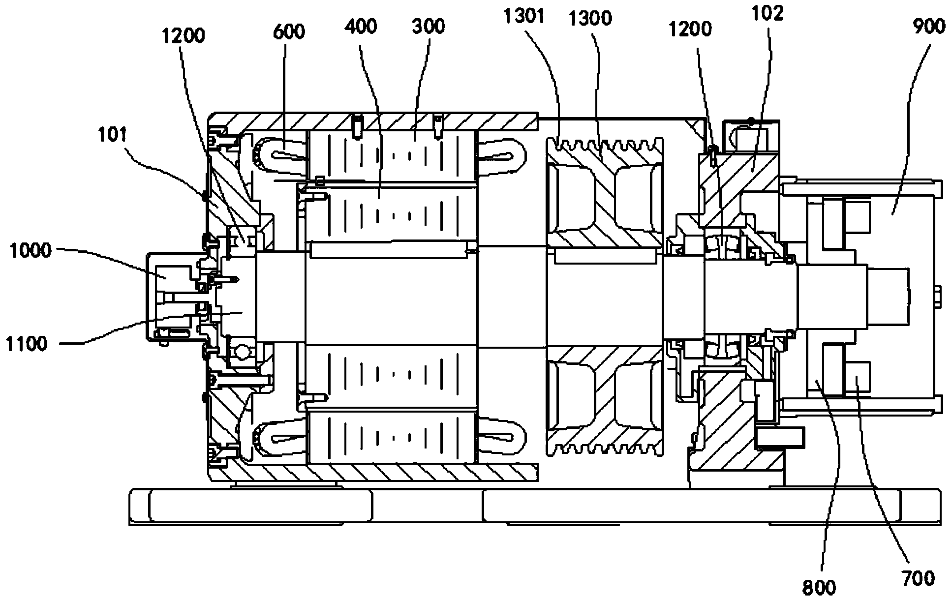
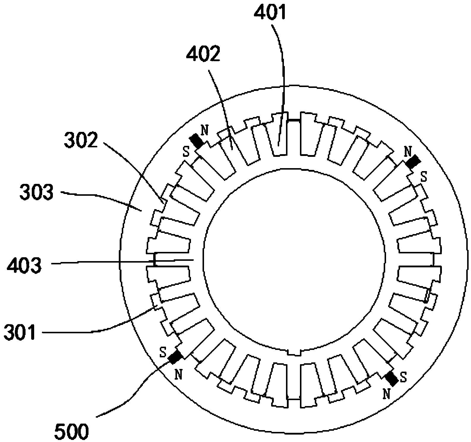
[0031] refer to figure 1 , 2 , in an embodiment of the present invention, an inner rotor permanent magnet synchronous reluctance traction drive device includes a brake 900, a support base, a rotating shaft 1100 rotatably mounted on the support base, and the support base includes a first support The seat 101 and the second supporting seat 102, the brake 900 is installed on the second supporting seat 102, and also includes the rotor core 400 sleeved on the rotating shaft 1100 and fixedly connected with the rotating shaft 1100, sleeved outside the rotor iron core 400 and fixed For the stator core 300 on the second support seat 102, the outer peripheral surface of the rotor core 400 is provided with a plurality of first grooves 401, and the inner peripheral surface of the stator core 300 is provided with a plurality of second grooves 301, at least Two permanent ...


PUM


Abstract

The invention discloses an inner rotor permanent magnet synchronous magnetic resistance type traction drive device which comprises a brake, a supporting seat and a rotating shaft rotatably mounted on the supporting seat, wherein the brake is mounted on the supporting seat. The inner rotor permanent magnet synchronous magnetic resistance type traction drive device further comprises a rotor and a stator, wherein the rotor is arranged on the rotating shaft in a sleeved mode and is fixedly connected with the rotating shaft, and the stator is arranged outside the rotor in a sleeved mode and is fixed on the supporting seat. A plurality of first grooves are formed in the surface of the outer circumference of the rotor, a plurality of second grooves are formed in the surface of the inner circumference of the stator, and permanent magnets are arranged on the bottoms of at least two second grooves. When the axis of the rotor is not aligned with the axis of the magnetic pole of the stator, detent force can act on the rotor to generate torque to enable the rotor to tend to the position with the smallest magnetic resistance, the torque pulsation of the rotor is reduced thereby, noise is reduced, and comfortableness of taking an elevator is improved. When a field winding is powered on, the paths of electro-excitation magnetic force lines and the paths of permanent magnet magnetic force lines form magnetic paths in parallel, the two magnetic fields and the rotor are overlaid at an air gap position, an air-gap field is improved, total magnetic flux of the air gap is increased, and noise is reduced.

Description

technical field [0001] The invention relates to the field of elevator drive devices, in particular to an inner rotor permanent magnet synchronous reluctance traction drive device. Background technique [0002] The traction drive device is the main drive device in the elevator, which is used to drive the elevator car to run up and down. The running stability of the traction drive device directly determines the stability of the elevator car, which will affect the comfort of passengers. Nowadays, the requirements for the safety and ride comfort of elevators are getting higher and higher, therefore, the requirements for traction drives are also getting higher and higher. [0003] The general traction driving device uses a permanent magnet synchronous motor. This kind of traction driving device needs to use a large number of rare earth permanent magnets. When the amount of rare earth permanent magnets is large, the cost will be high, which will increase the burden on the enterpri...

Claims


Application Information

Patent Timeline
IPC IPC(8): H02K21/28H02K1/24H02K1/14H02K1/17
Inventor 肖孝优郑光远张放
Owner HITACHI ELEVATOR GUANGZHOU
Why Eureka
Try Eureka