Rolled film formation apparatus
A film forming device and the technology of the film device, which are applied in the directions of winding strips, transportation and packaging, gaseous chemical plating, etc., can solve the problems of inability to form films and limited productivity, and achieve the effect of continuous formation.
- Summary
- Abstract
- Description
- Claims
- Application Information
AI Technical Summary
Problems solved by technology
Method used
Image

Examples
no. 1 approach ]
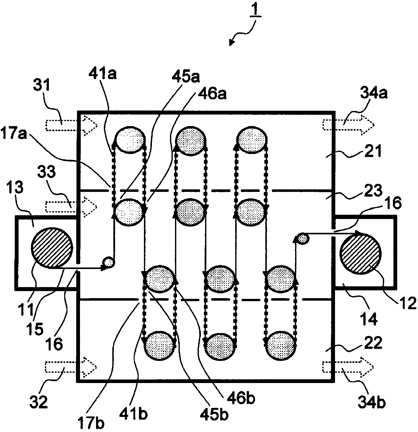
[0110] The roll-to-roll film forming apparatus according to the first embodiment of the present invention is shown in figure 1 .
[0111] The roll-to-roll deposition apparatus 1 according to the first embodiment of the present invention includes: a first vacuum chamber that is a first region 21 into which a first precursor gas is introduced; a second vacuum chamber that is a second region 22 into which a second precursor gas is introduced; And the third vacuum chamber that introduces the purge gas, that is, the third region 23 .
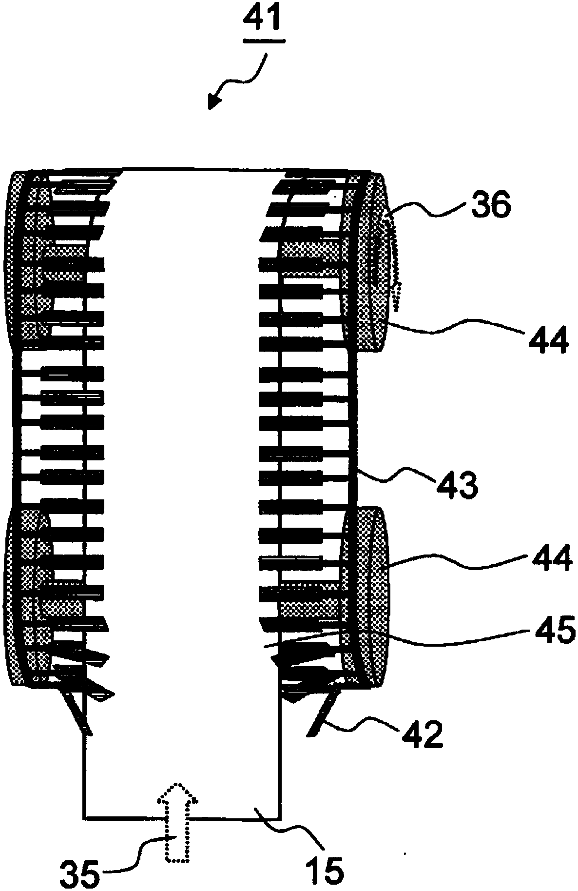
[0112] The roll-to-roll film forming device 1 is equipped with: an unwinding roller 11 arranged in the unwinding chamber 13; a winding roller 12 arranged in the winding chamber 14; 15 handling equipment 41a, 41b.
[0113] The transport devices 41a and 41b in the first embodiment of the present invention are clamps that transport the rollable base material 15 in a state where both ends in the width direction of the rollable base material 15 are clam...
no. 2 approach ]
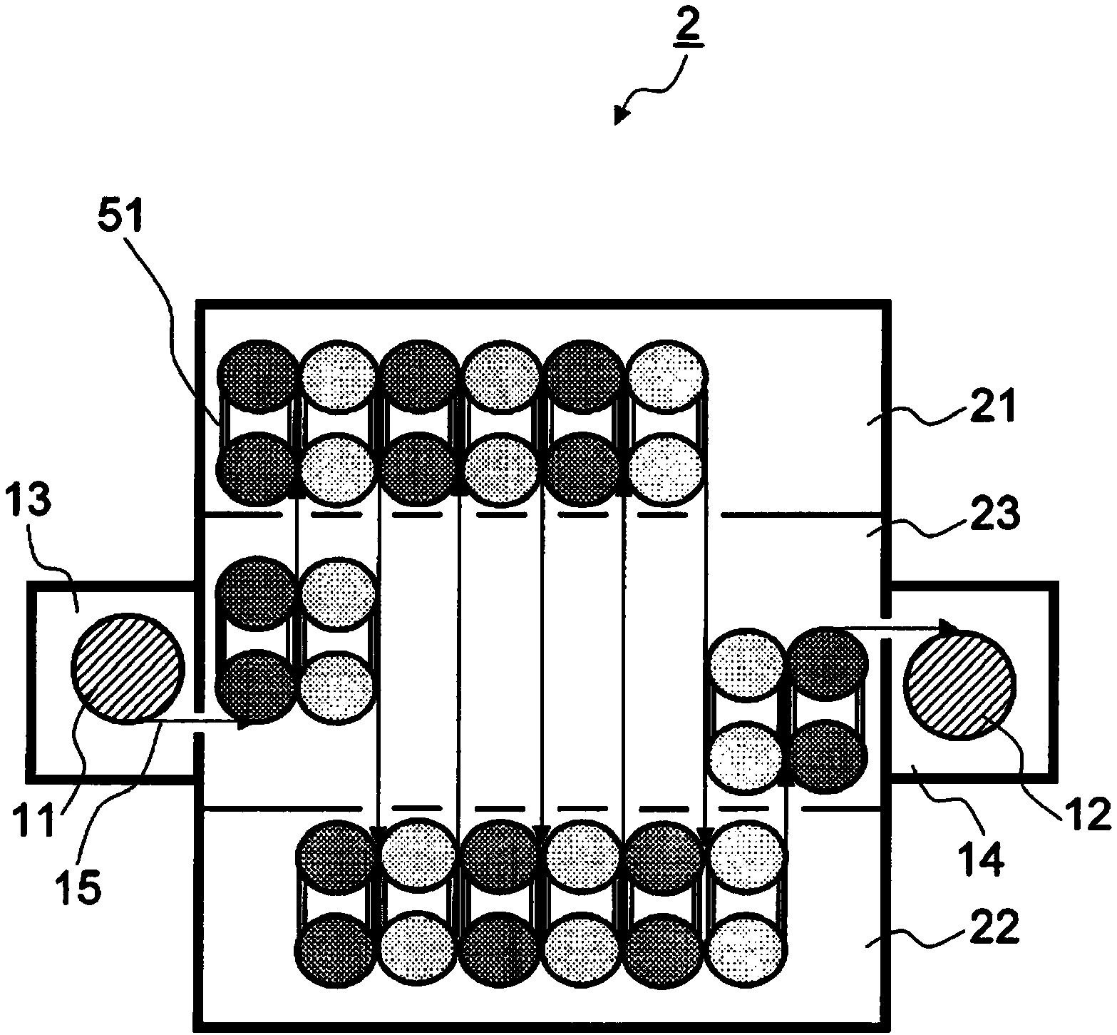
[0164] A roll-to-roll film forming apparatus according to a second embodiment of the present invention is shown in image 3 .
[0165] Similar to the roll-to-roll deposition apparatus 1 of the first embodiment of the present invention, the roll-to-roll deposition apparatus 2 of the second embodiment of the present invention includes: a first vacuum chamber, namely a first region 21, into which a first precursor gas is introduced; The second vacuum chamber, that is, the second region 22 , into which the second precursor gas is introduced; and the third vacuum chamber, that is, the third region 23 , into which the purge gas is introduced.
[0166] The film forming apparatus 2 is provided with: an unwinding roll 11 arranged in the unwinding chamber 13; a winding roll 12 arranged in the winding chamber 14; The handling equipment 51.
[0167] It should be noted that the configuration of the roll-to-roll film deposition apparatus 2 is the same as that of the roll-to-roll film deposi...
no. 3 approach ]
[0176] A roll-to-roll film forming apparatus according to a third embodiment of the present invention is shown in Figure 5 .
[0177] Similar to the roll-to-roll deposition apparatus 1 of the first embodiment of the present invention, the roll-to-roll deposition apparatus 3 of the third embodiment of the present invention includes: a first vacuum chamber that introduces a first precursor gas, that is, a first region 21; The second vacuum chamber, that is, the second region 22 , into which the second precursor gas is introduced; and the third vacuum chamber, that is, the third region 23 , into which the purge gas is introduced.
[0178] The film forming device 3 is provided with: an unwinding roll 11 arranged in the unwinding chamber 13; a winding roll 12 arranged in the winding chamber 14; The handling equipment 61.
[0179] It should be noted that the configuration of the roll-to-roll film forming apparatus 3 is the same as that of the roll-to-roll film forming apparatus 1...
PUM
| Property | Measurement | Unit |
|---|---|---|
| thickness | aaaaa | aaaaa |
| width | aaaaa | aaaaa |
| thickness | aaaaa | aaaaa |
Abstract
Description
Claims
Application Information
 - R&D
- Intellectual Property
- Life Sciences
- Materials
- Tech Scout
- Unparalleled Data Quality
- Higher Quality Content
- 60% Fewer Hallucinations
Browse by: Latest US Patents, China's latest patents, Technical Efficacy Thesaurus, Application Domain, Technology Topic, Popular Technical Reports.
© 2025 PatSnap. All rights reserved.Legal|Privacy policy|Modern Slavery Act Transparency Statement|Sitemap|About US| Contact US: help@patsnap.com