Method of controlling pitch systems of a wind turbine

A technology for wind turbines and controllers, applied in the directions of wind turbines, engine control, wind turbine control, etc., can solve problems such as power output reduction, and achieve the effect of reducing maintenance work and minimizing tower oscillation.

A technology for wind turbines and controllers, applied in the directions of wind turbines, engine control, wind turbine control, etc., can solve problems such as power output reduction, and achieve the effect of reducing maintenance work and minimizing tower oscillation.

CN103459837AInactive Publication Date: 2013-12-18SIEMENS AG

Image

  • Method of controlling pitch systems of a wind turbine
  • Method of controlling pitch systems of a wind turbine
  • Method of controlling pitch systems of a wind turbine

Examples


Embodiment Construction

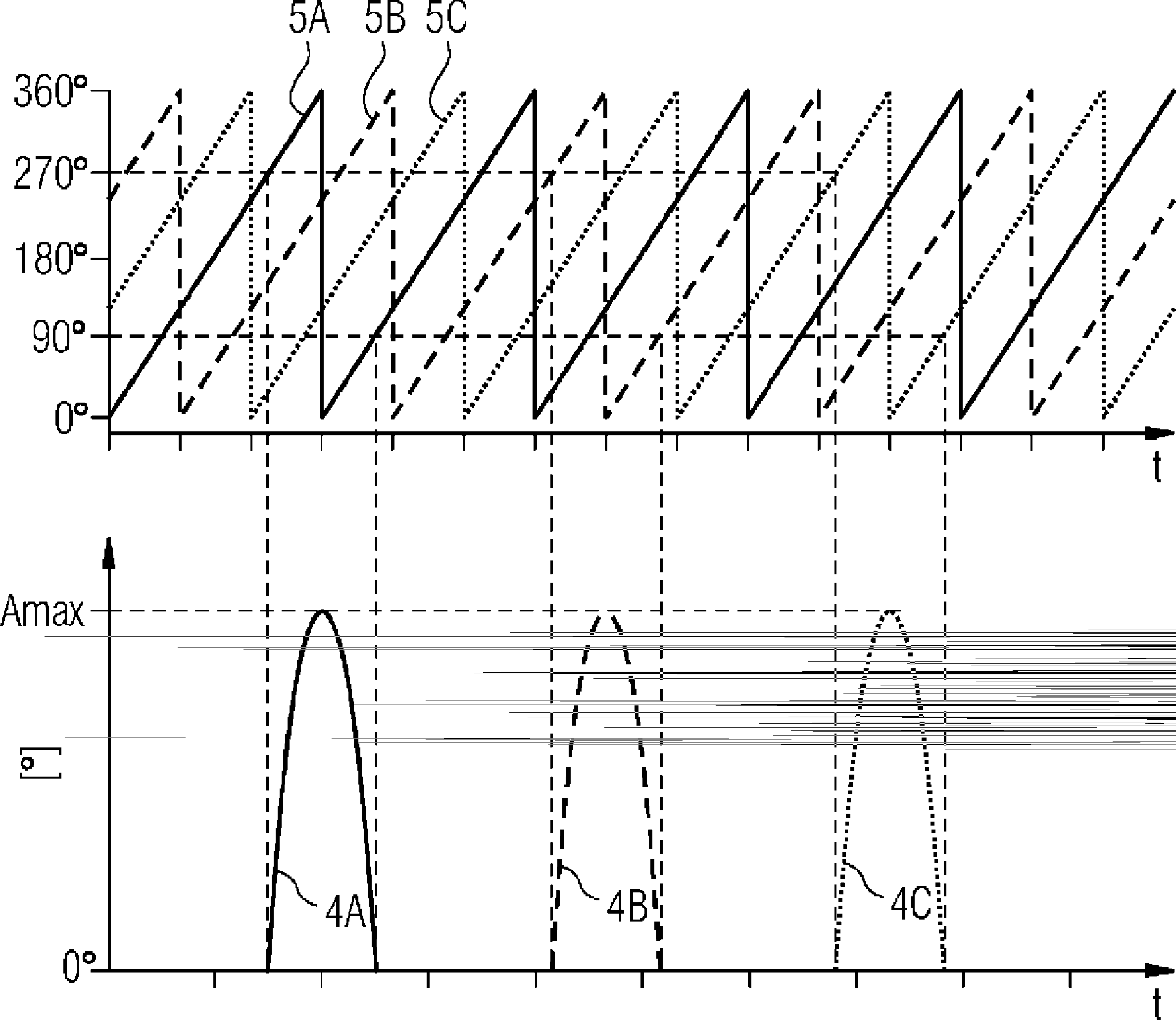
[0038] figure 1 An exemplary wind turbine 1 is shown with a nacelle 10 mounted on a tower 11 and a number of blades 3A, 3B, 3C connected to a hub 12 . When the wind W exerts a force on the blades 3A, 3B, 3C, they are caused to rotate (in this example, the blades 3A, 3B, 3C rotate clockwise when viewed from the front, as indicated by the arrow R). The wind turbine controller can drive the yaw ring to rotate the nacelle 10 in direction Y such that the hub 12 is substantially always facing the wind. The wind turbine controller is also able to control the pitch position of each rotor blade 3A, 3B, 3C such that the blades 3A, 3B, 3C are oriented at an optimal pitch angle. This allows the best possible conversion of wind energy into the rotational motion of the hub and rotor. The rotor blades 3A, 3B, 3C define a vertical plane P of rotation. The vertically arranged blade 3A in this figure is shown in a reference position at 0° in this plane P. As shown in FIG. When this blade 3A...


PUM


Abstract

The invention describes a method of controlling the pitch systems (2A, 2B, 2C) of a plurality of pitch systems (2A, 2B, 2C) of a wind turbine (1), which method comprises the steps of generating a main pitch control signal (600) for the pitch systems (2A, 2B, 2C) on the basis of a performance parameter of the wind turbine (1); generating a distinct auxiliary pitch control signal (4A, 4B, 4C) for each individual pitch system (2A, 2B, 2C) of the plurality of pitch systems (2A, 2B, 2C); adding an auxiliary pitch control signal (4A, 4B, 4C) to the main pitch control signal (600) to give a combined pitch control signal ( 6A, 6B, 6C) for a pitch system (2A, 2B, 2C); and controlling that pitch system (2A, 2B, 2C) in response to that combined pitch control signal ( 6A, 6B, 6C).; The invention also describes a pitch control system (6) for controlling the pitch systems (2A, 2B, 2C) of a plurality of pitch systems (2A, 2B, 2C) of a wind turbine (1), and a wind turbine (1) comprising a pitch control system (6) according to the invention.

Description

technical field [0001] The present invention describes a method of controlling a pitch system of a wind turbine, a pitch control system for controlling the pitch system of a wind turbine, and a wind turbine. Background technique [0002] Wind turbines generally comprise two or three rotor blades connected to a hub. Each blade is usually connected to the hub by means of a pitch system, the function of which is to allow the blade to rotate about its longitudinal axis to a certain degree in order to obtain an optimum pitch angle. To this end, a pitch actuator is used, such as an electric motor, a hydraulic piston or another type of actuator, to drive or rotate the pitch system by an appropriate amount. In order to allow the rotor blades to move relative to the hub. The pitch system houses bearings that are lubricated to minimize friction. [0003] The pitch angle of the rotor blades is adjusted to optimally capture power from the wind and can be controlled to maximize or lim...

Claims


Application Information

Patent Timeline
18 Dec 2013
Publication
CN103459837A
IPC
F03D7/02; F03D7/04
CPC
F03D7/0224; F03D7/024; F03D7/043; F05B2260/98; F05B2270/326; Y02E10/72
Inventors
T.埃斯本森; G.赫格