Thrust bearing holder and thrust bearing

A thrust bearing and cage technology, applied in the direction of bearings, bearing components, roller bearings, etc., can solve the problem that the cage cannot be applied, and achieve the effect of preventing detachment

Active Publication Date: 2013-12-18
NTN CORP
View PDF10 Cites 13 Cited by
  • Summary
  • Abstract
  • Description
  • Claims
  • Application Information

AI Technical Summary

Problems solved by technology

Therefore, resin-made cages may be chipped (cutted), so in the case of a three-in-one type, resin-made cages cannot be used

Method used


Image

  • Thrust bearing holder and thrust bearing
  • Thrust bearing holder and thrust bearing
  • Thrust bearing holder and thrust bearing

Examples


Embodiment approach 1

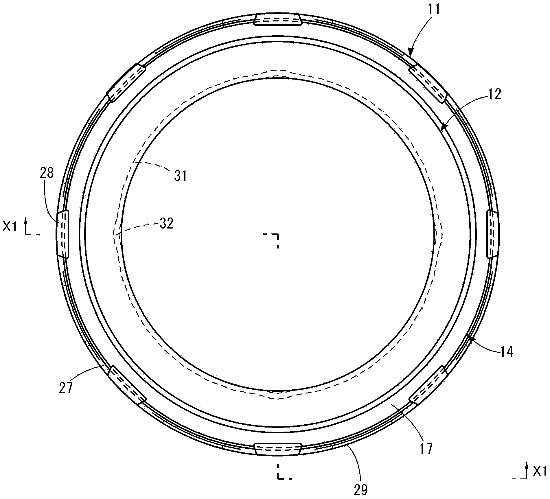
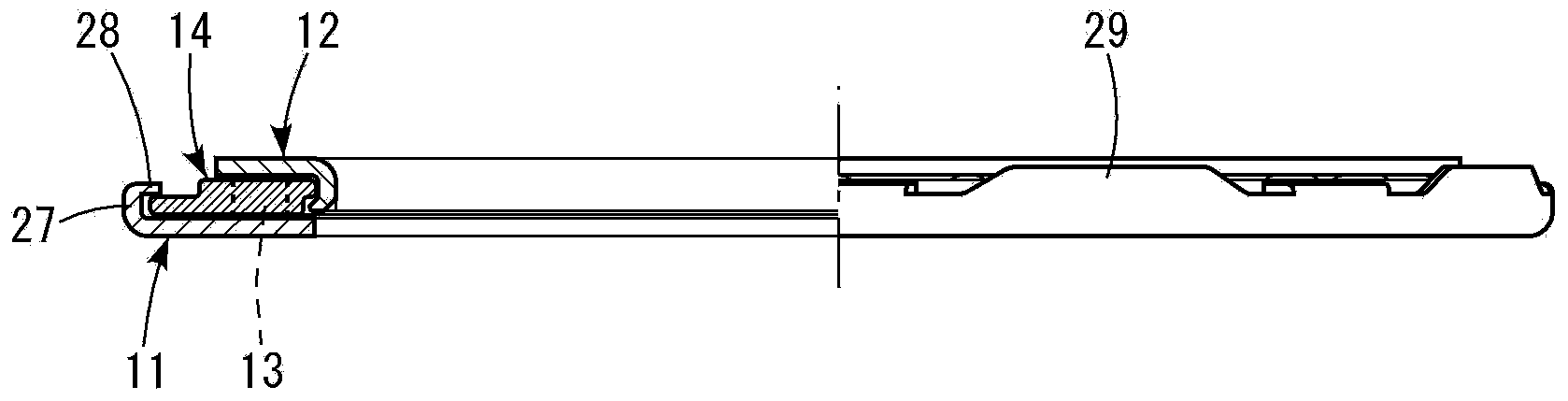
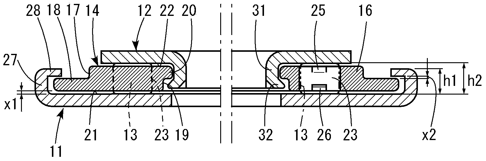
[0041] Figure 1 to Figure 5 The thrust bearing of Embodiment 1 shown includes an outer ring 11 and an inner ring 12 , a required number of rollers 13 interposed therebetween, and a cage 14 holding the rollers 13 .

[0042] The above-mentioned retainer 14 is formed by piercing a plate-shaped annular member 15 (refer to Figure 4 )form. A main body portion 16 having a constant (constant) thickness is formed in an intermediate portion in the width direction of the annular member 15 . A thin outer peripheral engagement edge 18 is formed on the outer peripheral edge of the main body portion 16 via a stepped portion 17 . In addition, on the surface opposite to the surface on which the above-mentioned outer peripheral engaging edge 18 is formed, a thin inner peripheral engaging edge 20 is formed on the inner peripheral edge via a step portion 19 .

[0043] The outer peripheral engaging edge 18 and the inner peripheral engaging edge 20 are formed by mechanical processing such as p...

Embodiment approach 2

[0054] Figure 12 to Figure 14 The thrust bearing according to the second embodiment shown is basically the same as that of the first embodiment described above, but in this second embodiment, as described above, the width of the outer circumferential engaging edge 18 of the cage 14 is set to be the same as that of the inner circumference. The widths of the circumferential clamping edges 20 are the same, which is suitable for the situation where the internal clearance of the bearing is relatively small. Therefore, since the engagement claw 28a provided on the front end edge of the flange 27 of the outer ring 11 may have a small protrusion amount, it is formed by press-and-recess engagement. The other configurations are the same as in the first embodiment described above.

Embodiment approach 3

[0056] Figure 15 The thrust bearing according to Embodiment 3 shown is composed of a combination of an outer ring 11 and a cage 14 holding rollers 13 . The holder 14 is different from the above-mentioned case in that the outer peripheral engaging edge 18 a formed on the outer peripheral edge of the main body portion 16 is tapered (tapered). Engagement claws 28 a are provided at the front end edge of the flange 27 of the outer ring 11 by press-and-recess engagement, and the outer ring 11 and the cage 14 are integrated with the engagement claws 28 a.

[0057] In addition, when the inner ring 12 is combined, a tapered inner peripheral engaging edge 20 a is formed on the surface of the body portion 16 opposite to the surface on which the outer peripheral engaging edge 18 a is formed.


PUM


Abstract

The present invention addresses the problem of providing a thrust bearing holder in which a roller is unlikely to come loose when the roller is accommodated in a pocket of a holder during the manufacturing stage. An annular member constituting a holder (14) is formed from a flat steel plate, a main body (16) is formed in a widthwise intermediate portion thereof, an outer peripheral engaging edge (18) lower than the surface of the main body is arranged at the outer peripheral edge of the main body (16), numerous pockets (23) passing through the thickness direction are arranged at equally spaced positions in the circumferential direction of the main body, and protrusions (25, 26) for retaining a roller (13) are formed in guiding surfaces of the pockets (23).

Description

technical field [0001] The present invention relates to a thrust bearing cage and a thrust bearing using the cage. Background technique [0002] In the thrust bearings used in automotive transmissions and torque converters, the range of the rolling surface of the mating member is limited, so it is sometimes necessary to make the roller length very short. [0003] When the length of the rollers is shortened, the attitude of the rollers when stored in the pockets of the cage becomes unstable, and there is a problem that the rollers tend to fall out of the pockets during the manufacturing process (refer to the patent document 1, figure 2 ). [0004] In order to prevent the rollers from falling off, it is necessary to deepen the pockets of the cage, and engage the outer diameter surfaces of the rollers at two locations as far away as possible from the centers of the rollers in the radial direction. As such a retainer, there is known a retainer in which an annular hollow porti...

Claims


Application Information

Patent Timeline
Patent Type & Authority Applications(China)
IPC IPC(8): F16C33/46F16C19/30
CPCF16C33/6681F16C19/305F16C33/541F16C33/543F16C33/467
Inventor 西川诚
Owner NTN CORP
Why Eureka
Try Eureka