Pneumatic feeding mechanism

A technology of discharging mechanism and feeding mechanism, applied in metal processing equipment, feeding device, manufacturing tools, etc., can solve the problems of wasting manpower, easy to cause industrial accidents, etc., and achieve the effect of reducing labor intensity

Active Publication Date: 2013-12-25
QIJING MACHINERY
View PDF6 Cites 9 Cited by
  • Summary
  • Abstract
  • Description
  • Claims
  • Application Information

AI Technical Summary

Problems solved by technology

[0002] The traditional pneumatic feeding mechanism needs to go through multiple stretching processes. The blank used is round cake material. When processing each time, one person needs to oil the round cake, and one person holds the round cake to the punch. After processing, use pliers to clamp The following problems exist in the production of semi-finished products: 2 people are required to operate a machine tool, which wastes manpower; manual loading and unloading of materials is prone to industrial accidents

Method used


Image

  • Pneumatic feeding mechanism
  • Pneumatic feeding mechanism
  • Pneumatic feeding mechanism

Examples


Embodiment Construction

[0010] The present invention will be further described below in conjunction with the accompanying drawings and specific embodiments.

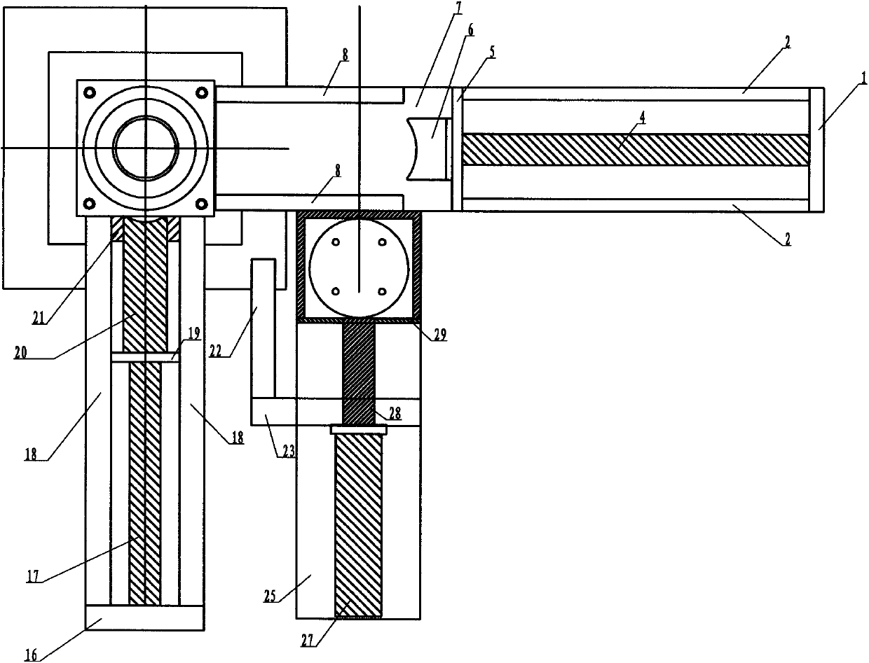
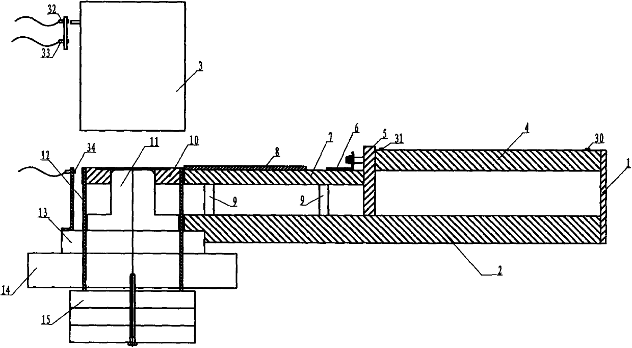
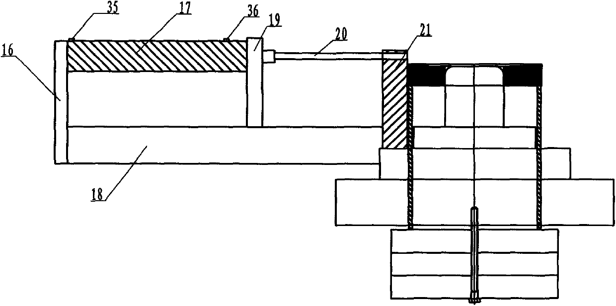
[0011] Please refer to the attached Figure 1 to Figure 4 As shown, a pneumatic feeding mechanism of the present invention, the pneumatic feeding mechanism includes a feeding mechanism, a stretching mold, and a mold ejection mechanism; the stretching mold is installed on the working plane of the punch press; the feeding module and the mold ejection mechanism are installed through support bars on the drawing die.

[0012] The drawing die includes a die 3 on the punching machine, a discharge plate 10, a lower convex head 11, a push rod 12, a convex head seat 13, a base 14, a rubber pad 15, an induction switch three 32, an induction switch four 33, an induction switch Switch five 34 . Described base 14 is installed on the machine tool platform; Protruding seat is fixed on the base; Protruding head 11 and induction switch 5 34 are installed on th...


PUM


Abstract

The invention relates to a pneumatic feeding mechanism. The pneumatic feeding mechanism comprises a feeding module, a drawing die and a mold mechanism; the feeding module further comprises a discharging mechanism and a feeding mechanism, wherein the discharging mechanism comprises a feed box, a discharging cylinder, a discharging push block, a discharging cylinder fixing plate and a discharing guide plate which are connected with each other; the discharging mechanism is fixed on the left front side of the drawing die through a support bar; the feeding mechanism comprising a feeding cylinder, a feeding cylinder fixing plate, a feeding push block, a feeding guide plate, a feeding guide plate and a feeding pressure plate is disposed in front of the drawing die through a support bar; the mold mechanism comprising a mold cylinder fixing plate, a mold push block, a mold cylinder, a guide block for the push block is mounted in the middle of the left side of the drawing die through a support bar; the drawing die comprises a lower protruding head, an upper die, a stripper plate, a mandrel, a protruding head seat, a base and a rubber pad which are connected with each other. The pneumatic feeding mechanism has the advantages of reducing labor intensity and improving production efficiency.

Description

technical field [0001] The invention relates to a pneumatic feeding mechanism. Background technique [0002] The traditional pneumatic feeding mechanism needs to go through multiple stretching processes. The blank used is round cake material. When processing each time, one person needs to oil the round cake, and one person holds the round cake to the punch. After processing, use pliers to clamp There are the following problems in the production of semi-finished products: 2 people are required to operate a machine tool, which wastes manpower; manual loading and unloading of materials is prone to industrial accidents. The invention provides a pneumatic feeding mechanism that realizes semi-automatic operation in the discharging process and reduces labor intensity. In the process of releasing the mold, the old-fashioned way of holding materials with pliers is removed, and the product is pushed out by the pneumatic side and directly falls into the basket ,save time and energy. ...

Claims


Application Information

Patent Timeline
Patent Type & Authority Applications(China)
IPC IPC(8): B21D22/02B21D43/02B21D45/04
Inventor 陈国良姚飞龙
Owner QIJING MACHINERY
Why Eureka
Try Eureka