Pressing plate vacuum chamber

A technology of vacuum chamber and pressure plate, which is applied in the direction of forming pressure head, etc., can solve the problems of complex structure of vibration motor heat dissipation system, increase of equipment weight and manufacturing cost, and difficult maintenance of internal components, so as to simplify the structure, overcome high manufacturing cost and reduce energy consumption. consumption effect

Inactive Publication Date: 2013-12-25
唐玮
View PDF2 Cites 7 Cited by
  • Summary
  • Abstract
  • Description
  • Claims
  • Application Information

AI Technical Summary

Problems solved by technology

In this technical solution, the heat dissipation system of the vibration motor has a complex structure and difficult maintenance of internal components; the indenter body is enclosed in a box-shaped vacuum chamber as a whole, and the billet must be sent under the indenter body for compaction, and the compacted billet must be sent out in the There are entrances and exits and frequently opened and closed sealing gates on the side wall of the vacuum chamber, and the mechanism is complex; the volume inside the vacuum chamber is large, which increases the time for vacuuming when pressing the plate, increases energy consumption, and reduces production efficiency; the external surface area of ​​the vacuum chamber is large, When vacuuming, the atmospheric pressure is correspondingly increased. In order to resist the atmospheric pressure, the vacuum chamber must be designed to be very thick, which increases the weight of the equipment and the manufacturing cost.

Method used


Image

  • Pressing plate vacuum chamber
  • Pressing plate vacuum chamber

Examples


Embodiment Construction

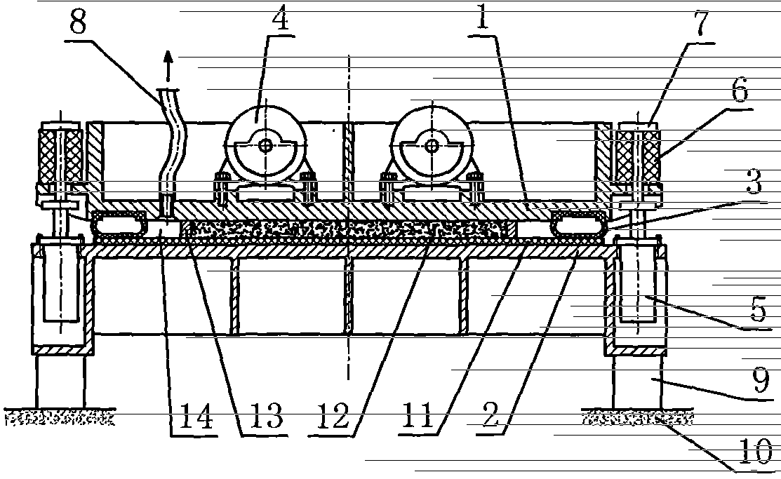
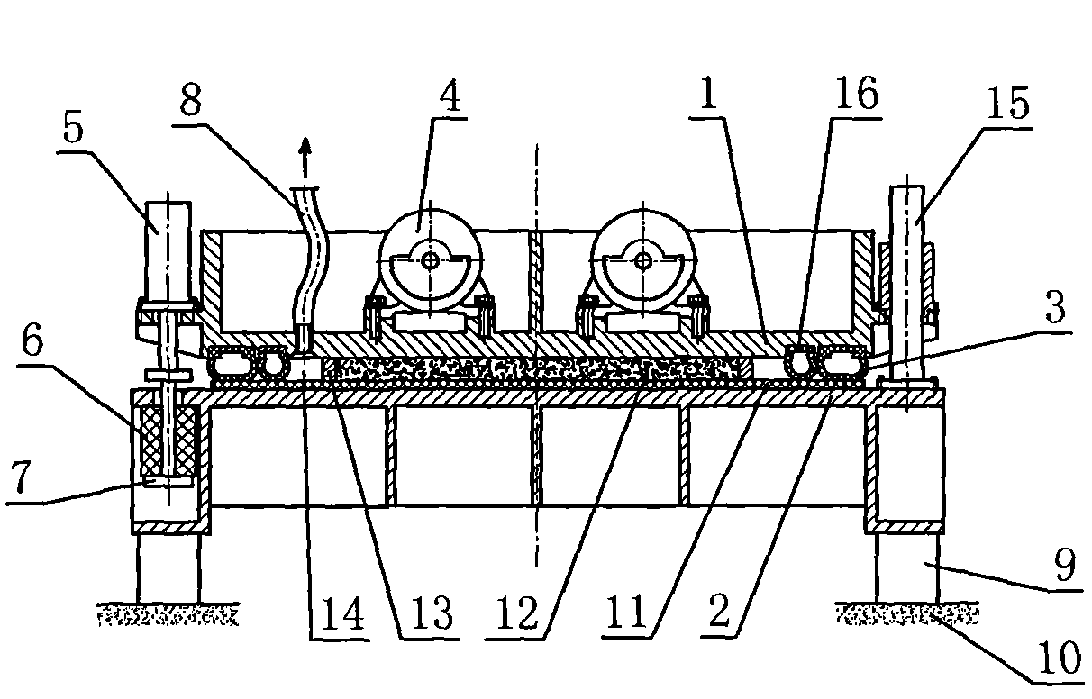
[0022] The specific implementation of the platen vacuum chamber of the present invention will be further described below in conjunction with the accompanying drawings:

[0023] figure 1 As shown: the embodiment of the pressure plate vacuum chamber of the present invention, the inflatable sealing ring 3 is arranged between the pressure head 1 and the base 2, and is fixed on the lower periphery of the pressure head 1. When working, the conveying belt 11 transports the blank 12 to the bottom of the pressure head 1, the lifting cylinder 5 moves to lower the pressure head 1, and the inflatable sealing ring 3 is lowered accordingly, and the blank 12 and the mold 13 are covered on the base 2, and the air is sealed. An airtight cavity 14 is formed between the inside of the ring 3 and the pressure head 1 and the base 2, and the airtight cavity 14 is evacuated through the vacuum tube 8 connected to the airtight cavity 14, and the lifting cylinder 5 fixed on the base 2 is connected to it...


PUM


Abstract

The invention relates to the technical field of sheet material molding. A pressing plate vacuum chamber comprises a pressing head and a base, wherein the pressing head is located above the base; the pressing head can be ascended and descended relative to the base; a sealing ring is arranged below the pressing head; when the pressing head is descended, a closed cavity is formed among the inner side of the sealing ring, the pressing head and the base; a blank and a mould are covered and closed in the closed cavity; the pressing head is provided with a vacuumizing pipe for communicating the outside with the closed cavity. According to the technical scheme, the sealing ring arranged between the pressing head and the base has various functions of sealing, bearing pressure, buffering, absorbing vibration, absorbing sounds, isolating sounds and the like; the capacity of the closed cavity is reduced so as to be good for shortening vacuumizing time, reducing energy consumption, improving the productivity and improving the product quality of a pressing plate; a main body steel structure is only composed of two members including the pressing head and the base, so that the structure is simplified, the manufacturing and maintenance costs are reduced and the vibration noises are reduced. The pressing plate vacuum chamber provided by the invention can be widely applied to pressing plate equipment pressed and molded in vacuum by an artificial sheet material.

Description

technical field [0001] The invention relates to the technical field of plate forming, in particular to a platen vacuum chamber used for vacuum press forming of man-made plates. Background technique [0002] In the prior art, in the press plate equipment used for vacuum press forming of man-made panels, the plate pressing process is carried out in a vacuum environment in a vacuum chamber, which is a closed cavity for vacuuming. Patent application number: 201020511763.X discloses "artificial stone slab press", the vacuum chamber is a closed cavity formed by a vacuum frame, an indenter and a base. The indenter and the vacuum frame are located above the base, and the indenter is set in the vacuum frame. The indenter and the vacuum frame are respectively equipped with lifting cylinders and guide columns to achieve vertical lifting and maintain the relative gap between the indenter and the vacuum frame. A vibrating motor is provided, and the vacuum frame is connected with a vacuu...

Claims


Application Information

Patent Timeline
Patent Type & Authority Applications(China)
IPC IPC(8): B28B3/04
Inventor 唐玮
Owner 唐玮
Why Eureka
Try Eureka