Pneumatic hydraulic jack

A pneumatic hydraulic jack technology, applied in the field of hydraulic jacks, can solve the problems of increased cost, increased turbulent flow, complex processing and manufacturing, etc., to achieve the effects of reducing temperature rise and pressure loss, prolonging service life, and increasing applicability

Inactive Publication Date: 2013-12-25
衡阳市锦泰工具有限公司
View PDF8 Cites 1 Cited by
  • Summary
  • Abstract
  • Description
  • Claims
  • Application Information

AI Technical Summary

Problems solved by technology

[0002] In the prior art, the oil circuit of the transition plate of the pneumatic hydraulic jack has many corners, and the hydraulic oil flow rate is relatively fast (2 m / s) during the working process. Friction will be generated when flowing through the corners, which will increase the temperature of the hydraulic oil, thereby affecting The service life of the system; more corners will increase the turbulent flow, which will increase the pressure loss of the hydraulic oil; the oil circuit is longer, the processing and manufacturing are complicated, and the cost increases
In addition, the diameter of the pressure relief piston in the prior art is Φ42mm. When the jack is used in the rated lifting range, the pressure relief piston of Φ42 mm can release the pressure normally, but when the jack is lifting heavy objects, it is often estimated by the operator Choose different types of jacks depending on the weight. When the lifting weight exceeds the rated lifting range of the jack, the Φ42 mm pressure relief piston cannot successfully complete the pressure relief action.

Method used


Image

  • Pneumatic hydraulic jack
  • Pneumatic hydraulic jack

Examples


Embodiment Construction

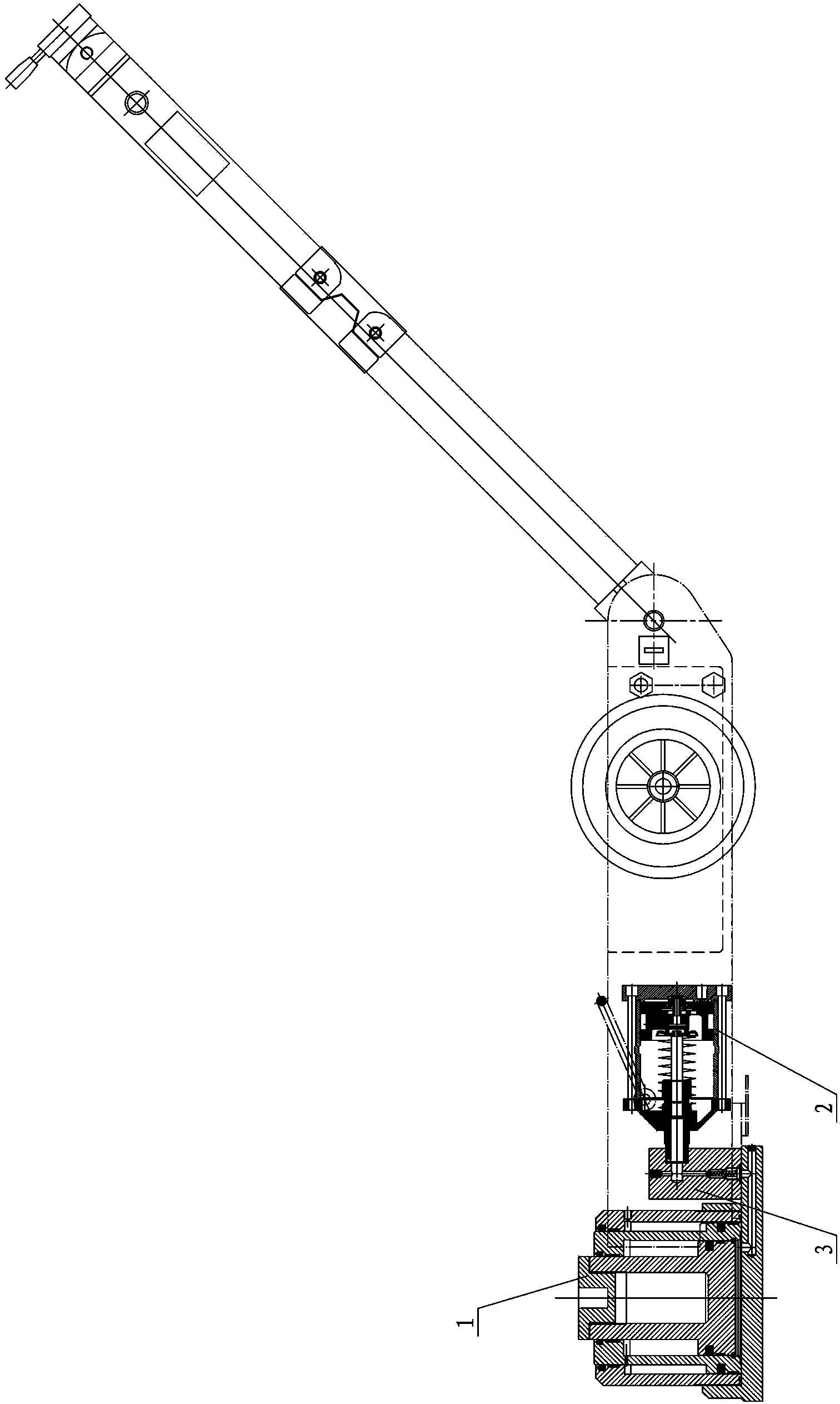
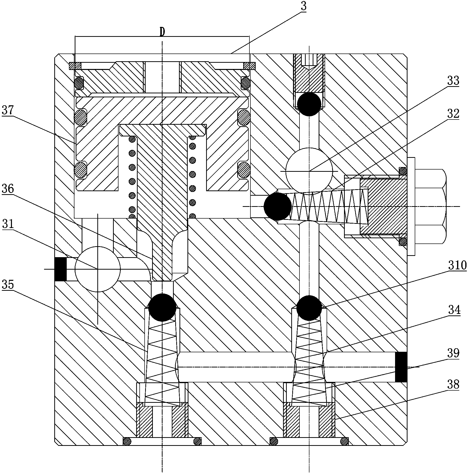
[0014] figure 1 A specific embodiment of the pneumatic hydraulic jack of the present invention is shown, and the pneumatic hydraulic jack includes a jacking cylinder 1 , an oil tank, a transition plate 3 and a pneumatic booster 2 . Such as figure 2 As shown, the transition plate 3 is provided with an oil supply passage and an oil return passage. The oil tank is connected to the jacking cylinder 1 through the oil supply passage on the transition plate 3, and the hydraulic oil pump is driven by the pneumatic booster 2 connected to the oil supply passage. Into the jacking cylinder 1, the oil supply channel of the transition plate 3 is provided with an oil inlet and outlet interface 31, a first check valve 32, a plunger pump interface 33 and a second check valve connected with the jacking cylinder 1 in sequence. 34, the second one-way valve 34 is arranged vertically and on the same axis as the plunger pump interface 33, and the first one-way valve 32 is horizontally arranged in ...


PUM


Abstract

The invention discloses a pneumatic hydraulic jack which comprises a jacking oil cylinder, an oil tank, a transiting plate and a pneumatic booster, wherein the oil tank is connected with the jacking oil cylinder through an oil supply channel on the transiting plate and is used for pumping hydraulic oil into the jacking oil cylinder through the pneumatic booster connected with the oil supply channel; an oil passing interface, a first one-way valve, a plunger pump interface and a second one-way valve are arranged in the oil supply channel; the oil passing interface, the first one-way valve and the plunger pump interface are communicated with each other in turn; the second one-way valve is communicated with the jacking oil cylinder; the second one-way valve is vertically arranged and is in a same axis with the plunger pump interface; the first one-way valve is arranged in the oil supply channel between the plunger pump interface and the second one-way valve; a third one-way valve is arranged in an oil return channel; the jacking oil cylinder is communicated with one end of the third one-way valve; the oil passing interface is communicated with the other end of the third one-way valve; and a pressure-relieving component for controlling the switch-on / off of the third one-way valve is arranged in the transiting plate. The pneumatic hydraulic jack provided by the invention has the advantages that the structure is simple, the oil-way corner is few, the friction of hydraulic oil is reduced, the temperature rise and pressure loss of the hydraulic oil are reduced and the jacking tonnage of the jack is increased.

Description

technical field [0001] The invention relates to the field of hydraulic jacks, in particular to a pneumatic hydraulic jack. Background technique [0002] In the prior art, the oil circuit of the transition plate of the pneumatic hydraulic jack has many corners, and the hydraulic oil flow rate is relatively fast (2 m / s) during the working process. Friction will be generated when flowing through the corners, which will increase the temperature of the hydraulic oil, thereby affecting In addition, more corners will increase the turbulent flow and increase the pressure loss of hydraulic oil; the oil circuit is longer, the processing and manufacturing are complicated, and the cost increases. In addition, the diameter of the pressure relief piston in the prior art is Φ42mm. When the jack is used in the rated lifting range, the pressure relief piston of Φ42 mm can release the pressure normally, but when the jack is lifting heavy objects, it is often estimated by the operator Choose ...

Claims


Application Information

Patent Timeline
Patent Type & Authority Applications(China)
IPC IPC(8): B66F3/24B66F3/25B66F3/26
Inventor 彭双喜
Owner 衡阳市锦泰工具有限公司
Why Eureka
Try Eureka