
Deslagging device

A slag discharger and slag storage technology, which is applied in the direction of feeding device, packaging, transportation and packaging, etc., can solve the problems of low production efficiency, long cooling time, safety accidents, etc., and achieve the goal of improving production efficiency and high safety and reliability Effect

Active Publication Date: 2013-12-25
宁波汇能环保科技有限公司
View PDF4 Cites 4 Cited by
  • Summary
  • Abstract
  • Description
  • Claims
  • Application Information

AI Technical Summary

Problems solved by technology

However, due to the extremely long cooling time of the equipment, and the refining equipment cannot be produced during cooling, the production efficiency is extremely low
Moreover, if the air leaks into the high-temperature reactor during the slag discharge process, the residue will easily ignite spontaneously in contact with air, resulting in a safety accident.

Method used


Image

  • Deslagging device

Examples


Embodiment Construction

[0015] The present invention will be further described below in conjunction with the accompanying drawings and specific embodiments.

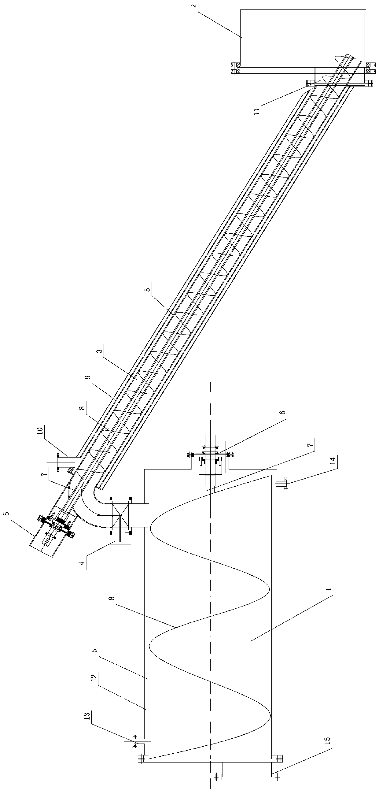
[0016] like figure 1 As shown, a slagging device of the present invention includes a slag storage tank 1 and a slagging machine 3 that is connected to the slag inlet and the reactor 2, that is, the slag inlet of the slagging machine 3 is connected to the reactor 2, and in this In the embodiment, the slag inlet of the slag discharger 3 goes deep into the bottom of the reactor 2; It communicates with the slag inlet of the slag storage tank 1 through a pipeline; the slag outlet of the slag storage tank 1 communicates with the outside air; The slag discharge port 14 of the slag storage tank is the slag discharge port of the slag storage tank 1 .

[0017] The structure of the slagging machine 3 and the slagging tank 1 is the same; that is, both have the following structure, but in this embodiment, the length of the slagging machine is greater than...


PUM


Abstract

The invention discloses a deslagging device which comprises a slag storage tank (1) and a deslagging machine (3), wherein a slag inlet of the deslagging machine (3) is communicated with a reaction kettle (2); a slag outlet of the deslagging machine (3) is communicated with a slag inlet of the slag storage tank (1); a slag outlet of the slag storage tank (1) is communicated with outside air; and a valve (4) is arranged on a communicating pipeline of the deslagging machine (3) and the slag storage tank (1). The deslagging device can perform deslagging during normal operation of refining equipment, and is high in deslagging safety and reliability.

Description

technical field [0001] The invention relates to an oil refining equipment system using waste plastics and waste rubber, in particular to a slag discharge device for the oil refining equipment. Background technique [0002] In the process of using waste plastics and waste rubber to crack and produce oil products in the oil refining equipment system, carbon residues will inevitably be generated in the reactor. The reason is that the hydrogen atoms in the high-molecular hydrocarbons of the reaction raw materials are separated from the original molecules under the action of high temperature, so that the carbon in the molecules is released. The free carbon forms a reaction residue together with uncrackable impurities in the raw material. The residue accumulates in the reaction process, more and more, occupying the limited volume of the reactor, thus affecting the normal operation of the reactor. Therefore just need to carry out slagging, and there is not slagging device in the ...

Claims


Application Information

Patent Timeline
Patent Type & Authority Applications(China)
IPC IPC(8): C10G1/00C10G1/10B01J4/00B65D88/68B65D88/74
Inventor 徐永安罗逸之罗名扬
Owner 宁波汇能环保科技有限公司
Learn More