Roller drive mechanism of quilting and embroidering machine allowing multiple pieces of cloth to be connected

A transmission mechanism and roller technology, which is applied to the mechanism of embroidery machines, embroidery machines, textiles and paper making, etc., can solve the problems of fabric waste and embroidery quality, unbalanced conveying speed, fabric wrinkle, etc., and reduce the chance of fabric wrinkling. , The effect of balanced conveying speed and balanced clamping force

Inactive Publication Date: 2013-12-25
陈展新
View PDF11 Cites 1 Cited by
  • Summary
  • Abstract
  • Description
  • Claims
  • Application Information

AI Technical Summary

Problems solved by technology

If the quilting embroidery machine of this structure wants to embroider multiple pieces of cloth side by side at the same time, its structure is simply to lengthen the machine, each piece of cloth is input separately, and each piece of cloth is not connected, which is equivalent to multiple The effect of using a single piece machine at the same time is that there are places on both sides of each piece of fabric that cannot be reached by embroidery needles, which reduces the embroidery area and wastes fabrics. Synchronized, and the fabric is guided by a roller of the feeding roller group, the fabric turns directly at 90 degrees without compression, which is likely to cause fabric wrinkles and affect the embroidery quality; so the ideal situation is to be able to convey all the fabrics in parallel. , cushioning, turning, changing direction and pressing, synchronous embroidery can not only greatly improve work efficiency and increase fabric embroidery area, reduce fabric waste, but also balance the conveying speed of each piece of fabric, easy to embroider synchronously, and the fabric is not easy to wrinkle To achieve this ideal situation, the following problems must be solved technically: because each roller must be lengthened in order to pass multiple pieces of fabric side by side, and the rigidity of the rollers needs to be strengthened after lengthening. If the rigidity needs to be strengthened It is a technical problem to increase the support at the rigid support point of the roller, which affects the smooth passage of the cloth. However, in the prior art, including domestic and foreign counterparts, multiple cloths are embroidered separately and side by side only to improve work efficiency. There is no method to solve the above-mentioned cloth waste and embroidery quality problems, and there is no technical solution to solve this technical problem. Therefore, there has not been a multi-pile connecting quilting machine roller transmission mechanism with the function of connecting multiple pieces of cloth side by side for embroidery.

Method used


Image

  • Roller drive mechanism of quilting and embroidering machine allowing multiple pieces of cloth to be connected
  • Roller drive mechanism of quilting and embroidering machine allowing multiple pieces of cloth to be connected
  • Roller drive mechanism of quilting and embroidering machine allowing multiple pieces of cloth to be connected

Examples


Embodiment Construction

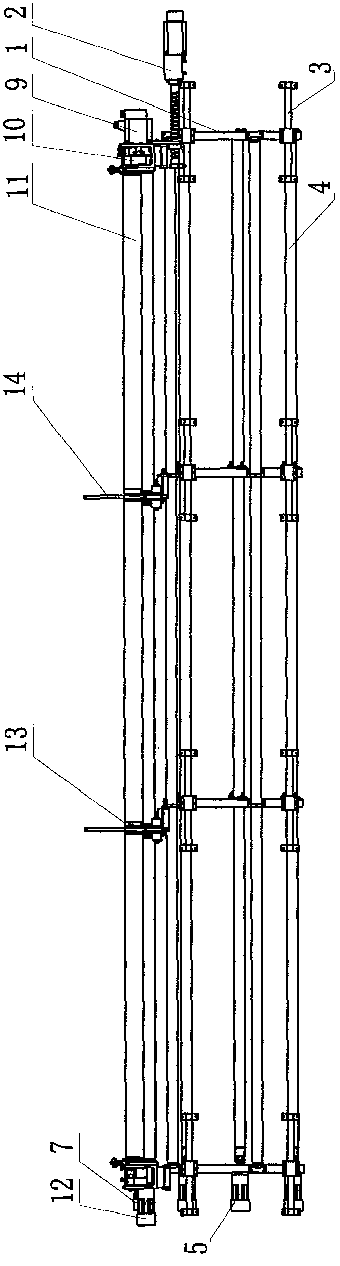
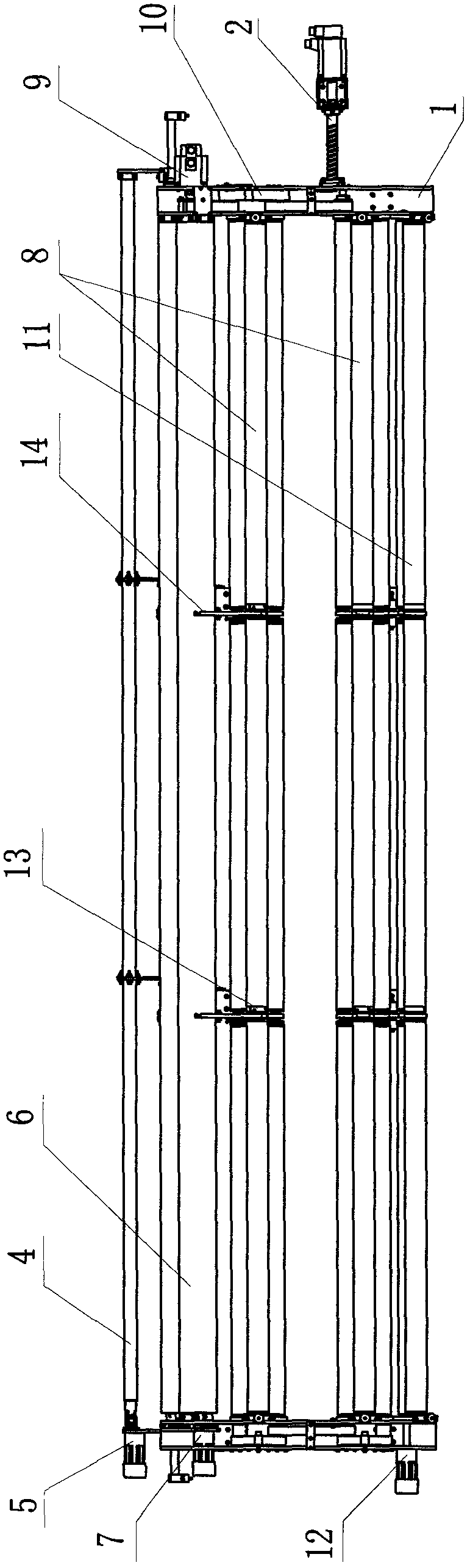
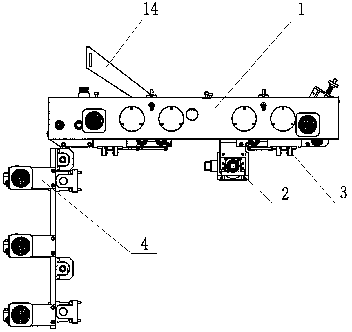
[0047] Depend on Figure 1-31As shown, the embodiment of the multi-piece connection quilting embroidery machine roller transmission mechanism of the present invention is: including the saddle frame 1 that is installed on the quilting embroidery machine frame to support the entire roller transmission mechanism and the X axial movement that moves it axially. The device 2 and the X-axis guide rail device 3 include the cloth coil feed roller group 4 installed on the saddle frame 1 and the coil feed drive motor 5 that drives it, and the feed roller group 6 and the feed drive device 7 that drives it , there is also a tensioning roller group 8 and the tensioning drive motor 9 and the transmission device 10 driven by it, as well as the discharging roller group 11 and the discharging driving motor 12 driven by it, and the described cloth roll delivery roller group 4 , the feeding roller group 6, the tensioning roller group 8 and the discharging roller group 11 can all pass through at l...


PUM


Abstract

The invention discloses a roller drive mechanism of a quilting and embroidering machine allowing multiple pieces of cloth to be connected. The roller drive mechanism comprises a saddle frame, an X-axis axial mobile device, an X-axis axial guide rail device, a cloth rolling feeding roller set, a rolling feeding drive motor, a feeding roller set, a feeding drive device, a tension roller set, a tension drive motor, a transmission device, a discharging roller set and a discharging drive motor. All the roller sets can allow at least two pieces of cloth to pass through side by side; the rigid bearing points of all the roller sets are supported by bearing support devices; the cloth rolling feeding roller set is provided with three reel rollers, and the positions of the reel bearing support devices of the reel rollers in the vertical direction are mutually staggered so that the edges of the cloth on different rollers can be connected in a splicing or spliced mode; the feeding roller set is provided with a guiding roller, two feeding rollers and feeding bearing support devices; the tension roller set is provided with two three-roller roller sets and a tension bearing support device, and the lower surface of a bearing pedestal of the tension bearing support device is provided with a notch; the discharging roller set is provided with discharging rollers, clamping rollers and a discharging bearing support device, and the lower surface of a bearing pedestal of the discharging bearing support device is provided with a notch. The roller drive mechanism has the advantages that the multiple pieces of cloth can be connected together side by side and conveyed for synchronous embroidering, the embroidery area of the cloth is increased, the cloth is not prone to creasing, and efficiency and quality are improved.

Description

technical field [0001] The invention relates to a roller transmission mechanism of a quilting embroidery machine, in particular to a roller transmission mechanism of a multi-piece connecting quilting embroidery machine which can simultaneously quilting and embroidering multiple pieces of cloth side by side. Background technique [0002] In the prior art, the quilting embroidery machine is a new type of advanced industrial quilting machine that can both quilt and embroider. It is widely used in home textiles, clothing, bags, handbags, shoes and hats, etc. , chemical fiber, silk lace, and other fabrics and leather single or multi-layer, according to the quilting, quilting embroidery pattern program, for various styles of quilting and embroidery. The roller transmission mechanism of the quilting embroidery machine mainly includes the saddle mounted on the quilting embroidery machine frame to support the entire roller transmission mechanism, the X-axis swing device and the X-axi...

Claims


Application Information

Patent Timeline
Patent Type & Authority Applications(China)
IPC IPC(8): D05C9/00D05C9/20
Inventor 陈展新
Owner 陈展新
Why Eureka
Try Eureka