Dislocated expansion joint structure of bridge structural breaking joint

A bridge structure and expansion joint technology, applied in bridges, bridge parts, bridge construction, etc., can solve the problems of large batch stress, complex force, and short service life of key parts, so as to avoid major safety accidents, prolong service life, The effect of improving the stress condition

Inactive Publication Date: 2013-12-25
CHONGQING JIAOTONG UNIVERSITY
View PDF5 Cites 4 Cited by
  • Summary
  • Abstract
  • Description
  • Claims
  • Application Information

AI Technical Summary

Problems solved by technology

[0004] However, because the main body of the expansion joint device of the above-mentioned structure is located directly above the broken seam of the bridge structure, the main body of the expansion device with weak structural performance is just located at the weak broken joint of the bridge structure. The telescopic device has problems such as low reliability of force transmission, complex force, large batch stress on key parts, easy damage, and short service life.

Method used


Image

  • Dislocated expansion joint structure of bridge structural breaking joint
  • Dislocated expansion joint structure of bridge structural breaking joint

Examples


Embodiment Construction

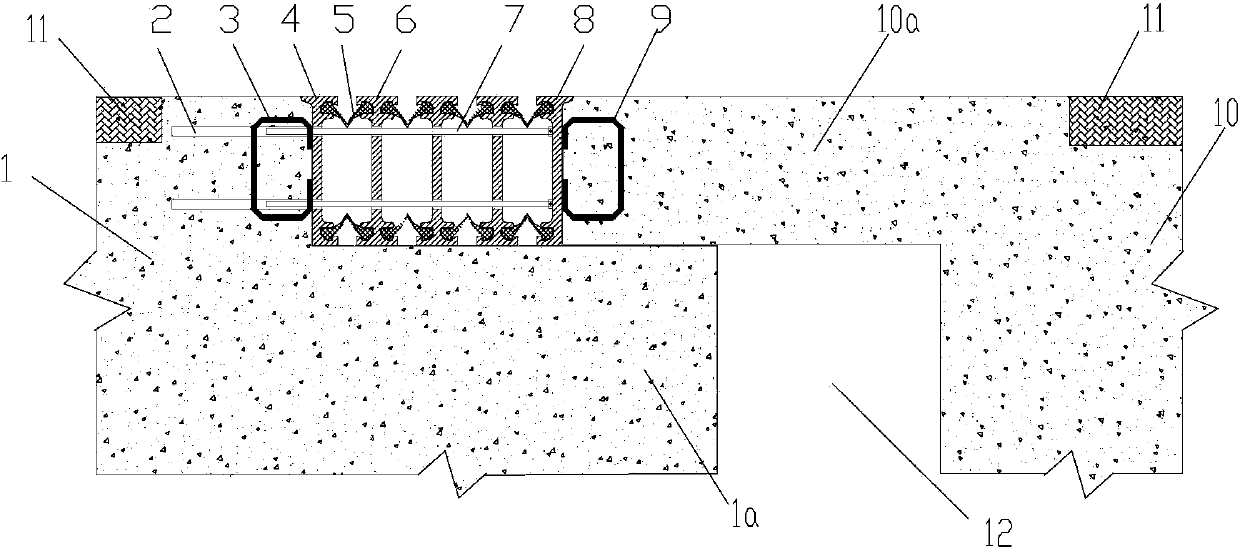
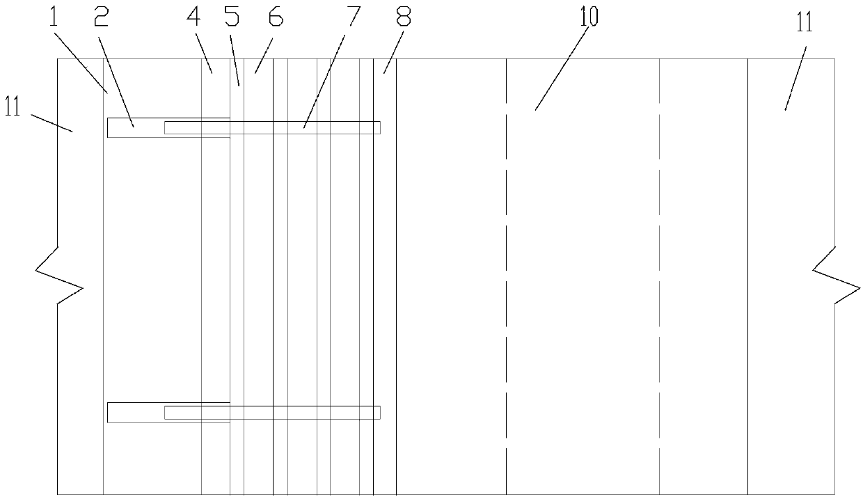
[0022] figure 1 It is a schematic diagram of the structure of the present invention, figure 2 for figure 1 As shown in the figure: the dislocation expansion joint structure of the bridge structure in this embodiment includes the structural fracture 12 and the expansion joint longitudinally dislocated with the structural segment joint 12, and the expansion joint longitudinally dislocated with the structural segment joint 12 It is formed by the partial longitudinal extension of the structure on one side of the structural fracture, crossing the structural fracture and overlapping the structure on the other side; as shown in the figure, the two structures (structure 1 and structure 10) that form the structural segment seam, one side of the structure 10 partially extends longitudinally And overlapped with structure 1; the overlapping structure refers to the superposition of the two in the up and down direction, one side of which can bear the downward pressure on each other and fo...


PUM


Abstract

The invention discloses a dislocated expansion joint structure of a bridge structural breaking joint. The dislocated expansion joint structure of the bridge structural breaking joint comprises the structural breaking joint and an expansion joint which are longitudinally dislocated. The one side structure of the structural breaking joint locally and longitudinally extends to cross the structural breaking joint to be in overlap connection with the other side structure to form the expansion joint. According to the dislocated expansion joint structure of the bridge structural breaking joint, coincidence of an extensible device main body which is weak in structural performance and the bridge structural breaking joint in the same vertical position is avoided, vehicle loads can be directly transferred to the step surface of a subsidence step of an expansion joint pavement device through side beams and an intermediate beam due to the expansion joint pavement device which is a non-beam type stress working component, the structure edge which is connected with the expansion joint device can be difficult to be damaged due to wrap angles which are formed on the upper portions of the side beams, the structure of the expansion joint device is greatly simplified, the stress condition of the integral expansion joint structure is improved, the bearing capability of the expansion joint device is improved, the service circle of the expansion joint device is extended, and serious safety accidents caused by damage of the expansion joint are avoided.

Description

technical field [0001] The invention relates to an auxiliary structure in the field of civil engineering, in particular to a construction of dislocation expansion joints of broken joints in a bridge structure. Background technique [0002] Bridge expansion joints are used to adapt to the deformation of the bridge under the action of various factors (temperature change, creep deformation, load action, uneven foundation settlement and earthquake), and to avoid cracking or even damage. The expansion joints are artificially set across the structural cracks. [0003] In the prior art, multi-group bridge expansion joint devices are widely used, and are composed of profiled steel side girders, profiled steel center girders, supporting beams, displacement control boxes, pressure bearings, compression bearings, anchoring steel plates, and anchoring steel bars. And bird-shaped sealing rubber belt composition. It is a composite upgraded product of a single group of bridge expansion jo...

Claims


Application Information

Patent Timeline
Patent Type & Authority Applications(China)
IPC IPC(8): E01D19/06
Inventor 杨旸
Owner CHONGQING JIAOTONG UNIVERSITY
Why Eureka
Try Eureka