Supercharge Your Innovation With Domain-Expert AI Agents!

Mechanical flushing squatting pan

A technology for squatting toilets and flushing, applied in water supply devices, flushing equipment with water tanks, buildings, etc., can solve the problems of potential safety hazards, non-flushing toilets, poor toilet environment, etc., achieve compact structure, no potential safety hazards, and improve The effect of degrees of freedom

Inactive Publication Date: 2013-12-25
NORTHWEST A & F UNIV
View PDF2 Cites 4 Cited by
  • Summary
  • Abstract
  • Description
  • Claims
  • Application Information

AI Technical Summary

Problems solved by technology

Manual flushing devices generally use manual switches or foot switches. People need to flush after going to the toilet. Automatic flushing cannot be completed, which is a waste of time. The toilet environment is poor, so some people develop the habit of not flushing the toilet.
There are electrical and mechanical types of automatic flushing devices. Electric flushing devices use sensors to sense the presence of users when people go to the toilet, and automatically flush when people leave. However, electric flushing devices are expensive and safe. Hidden dangers, power failure and other disadvantages hinder its application; Chinese Patent No. 201220441305.2 proposes a fully automatic contact flush valve with an integrated reverse water curved squat toilet. When the user steps on the pedal when going to the toilet, the water storage tank automatically stores water , the reservoir automatically flushes when the user leaves, and when the lower limit is reached, the flushing stops automatically
Although the above-mentioned patents can realize automatic flushing, the flushing occurs when the user's feet leave the pedal, and if the user needs to flush during the toilet due to physical or other reasons, the above patents are difficult to solve
Chinese Patent No. 201210183658.7 proposes a toilet that uses pedals to flush water at any time, which can flush the toilet at any time, but it is not suitable for squatting toilets

Method used


Image

  • Mechanical flushing squatting pan
  • Mechanical flushing squatting pan
  • Mechanical flushing squatting pan

Examples


specific Embodiment approach 1

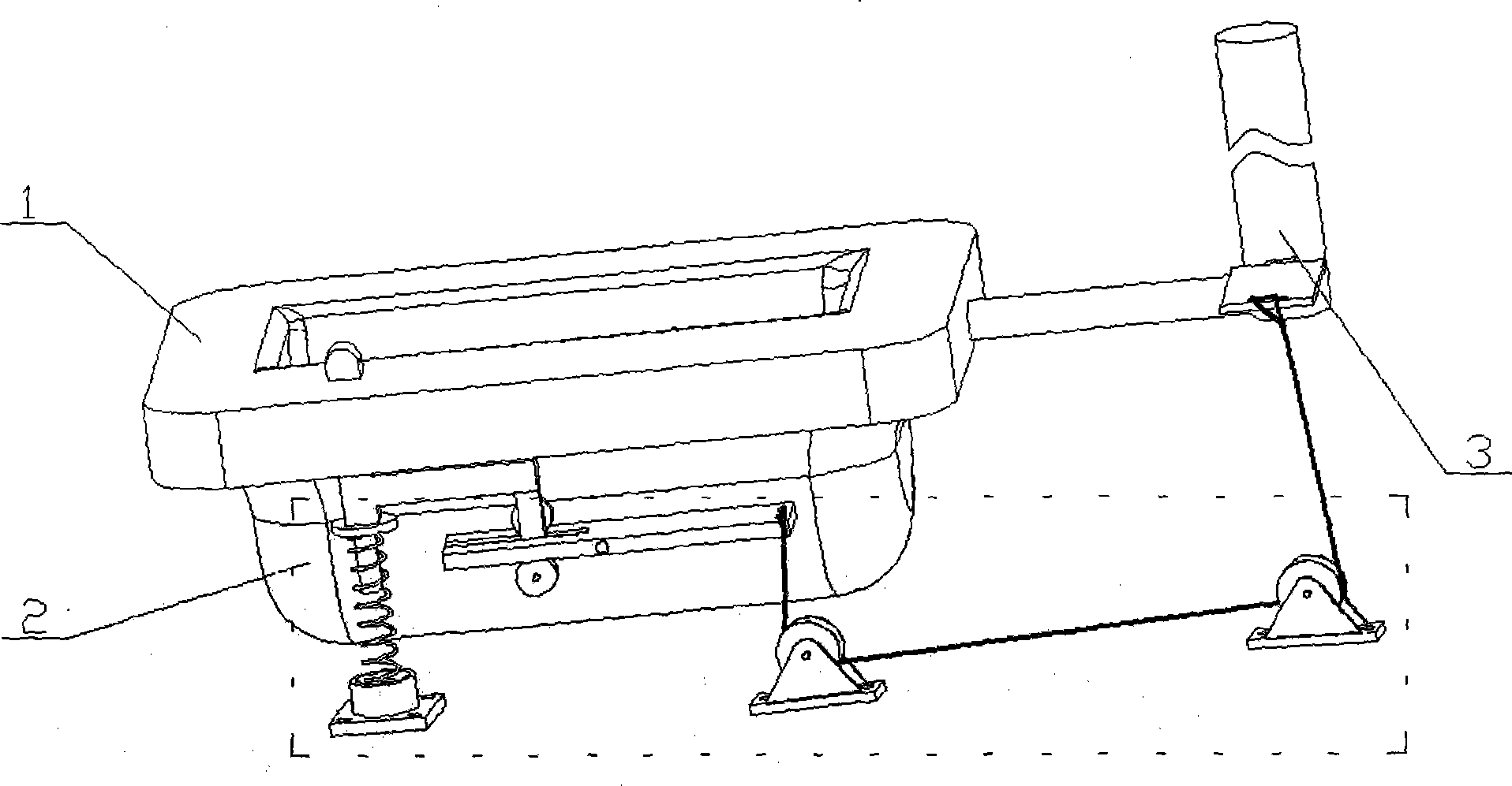
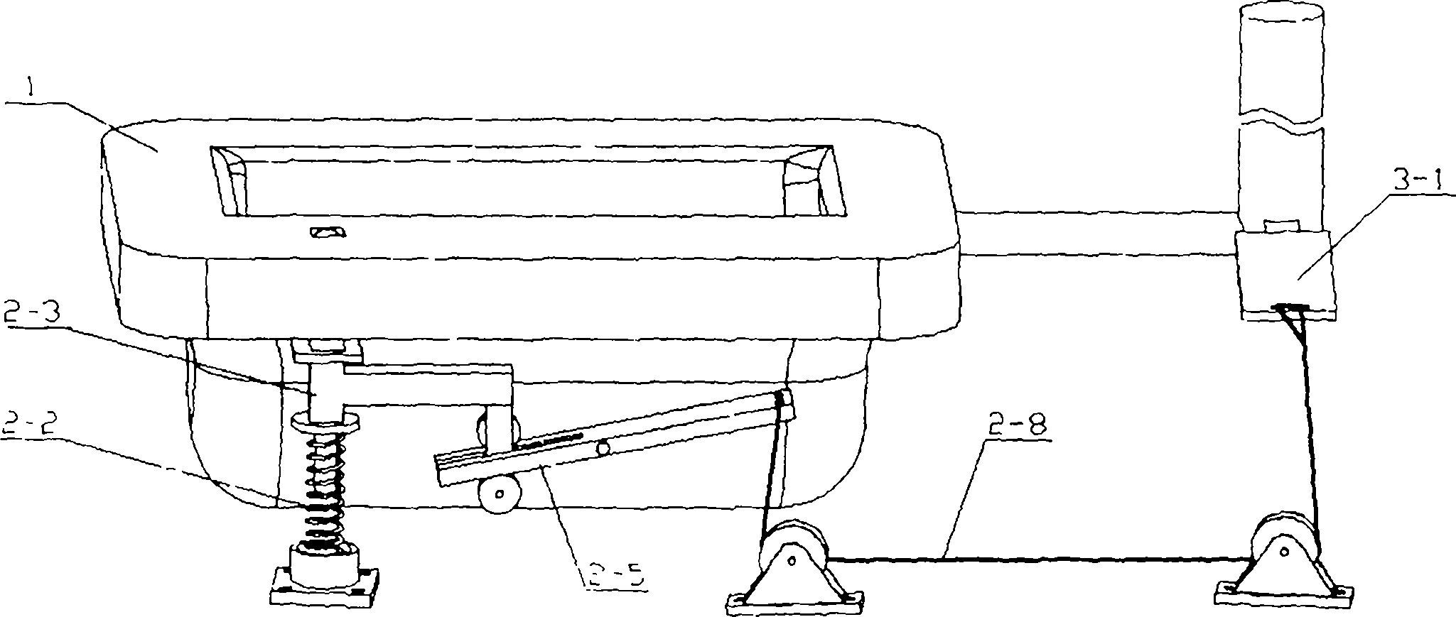
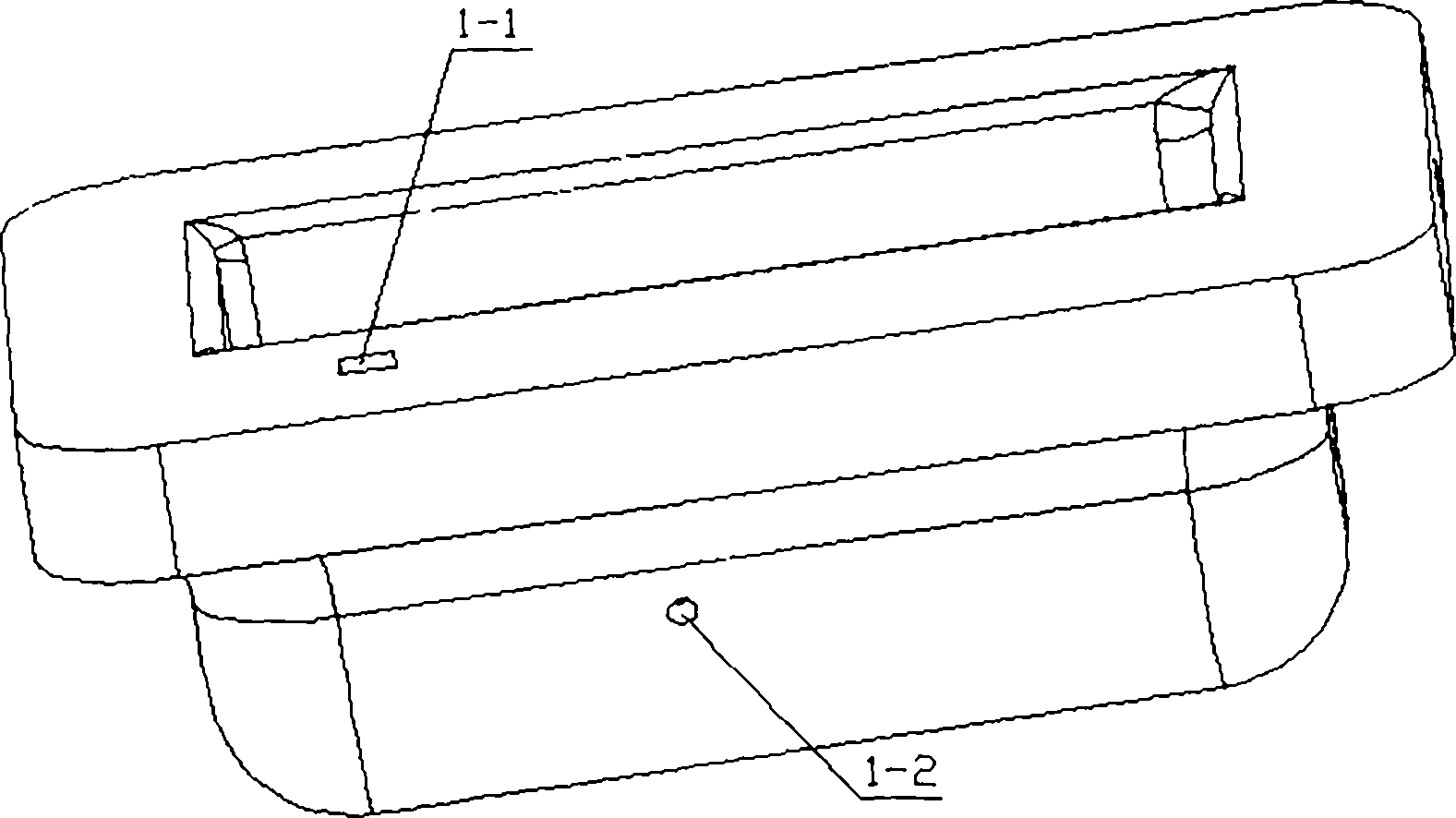
[0021] like figure 1 , image 3 As shown, the squatting pan includes a bedpan 1 , a transmission part 2 and a flushing part 3 . The bedpan is provided with a rectangular through hole 1-1 and a threaded blind hole 1-2, and the end of the flushing pedal 3-1 of the flushing component 3 is provided with a fixing hole for fixing a steel wire. The bedpan 1 and the flushing part 3 can directly use existing products on the current market, and process the rectangular hole through hole 1-1 and the threaded blind hole 1-2 at suitable positions on the surface and side of the bedpan 1, while the flushing part 3 only needs The end of the selected product can be processed with two through holes. In order to facilitate the fixing of steel rope 2-8 wire ends, at least two steel wire clips are required.

specific Embodiment approach 2

[0022] like Figure 4 , Figure 5 , Image 6 , Figure 7 , Figure 8 As shown, the transmission part 2 includes a spring base 2-1, a return spring 2-2, a moving rod 2-3, a roller one 2-4, a roller two 2-5, a rotating plate 2-6, and a rotating shaft 2-10 , pulley one 2-7, pulley two 2-9 and steel rope 2-8. Return spring 2-2 is vertically fixed in spring base 2-1, and spring base 2-1 is installed on the ground. The moving rod 2-3 includes the top 2-3-1 of the moving rod, the limit plate 2-3-2, the spring baffle 2-3-3, the spring guide rod 2-3-4, and the middle part of the moving rod 2-3-5 , moving rod tail 2-3-6 and two roller shafts 2-3-7, 2-3-8; moving rod top 2-3-1 section is rectangular, and it slides with the rectangular through hole 1-1 on the bedpan Cooperate; the limit plate 2-3-2 cooperates with the lower end face of the bedpan, and limits the maximum height that the moving rod 2-3 rises under the restoring force of the return spring 2-2; the spring baffle plate 2...

specific Embodiment approach 3

[0024] figure 1 , Figure 9 As shown, since the installation ground of the bedpan is mostly cement floor, when installing the flushing device, according to the actual space position of the bedpan 1 and the installation position of the flushing device 3, the spring base can be installed first by using expansion screws or anchor bolts 2-1 and two pulleys 2-7, 2-9. For the convenience of installation, the spring base and the two pulleys should be installed on the same plane as far as possible. Need to be decided by the position of bedpan 1 and flush pedal 3-1. After spring base and two pulleys are installed, other parts are installed again, and steel rope 2-8 is then installed at last, and steel rope will be adjusted to suitable length when steel rope 2-8 is installed. When the steel rope is installed, the two pulleys and the steel rope should be protected by round pipes and U-shaped pipes, etc., so that the pulleys and the steel rope can move freely without being buried. Whe...


PUM


Abstract

The invention relates to a mechanical flushing squatting pan, belongs to the technical field of bathroom accessories, and aims to provide a set of device capable of conveniently flushing a bed pan at any time during defecation. The squatting pan comprises the bed pan, a transmission part and a flushing part, wherein the transmission part comprises a spring base, a reset spring, a moving rod, a first roller, a second roller, a rotating plate, a rotating shaft, a first pulley, a second pulley and a steel rope. When the top of the moving rod raising from the surface of the bed pan is pedaled, the moving rod downwards moves, the rotating plate rotates, the steel rope is stretched, a flushing pedal of the flushing part is downwards pulled, and the flushing part starts flushing the bed pan; when pressure is removed by a user, the flushing part stops flushing the bed pan, and is reset under the action of restoring force of the flushing pedal and the reset spring. When the mechanical flushing squatting pan is used, the user can flush the bed pan at any time during defecation, so that the comfort of the user is greatly improved; a purely mechanical structure is adopted, the mechanical flushing squatting pan is hidden in the ground, and is compact in structure and durable, and potential safety hazards are eliminated.

Description

technical field [0001] The invention relates to a squatting pan, in particular to a mechanical flush squatting pan. Background technique [0002] Family and communal toilet widely adopt squatting pan, and existing squatting just flushing device has manual flushing device and automatic flushing device. The manual flushing device generally adopts a manual switch or a foot switch. People need to flush water after going to the toilet. Automatic flushing cannot be completed, which is a waste of time. The toilet environment is poor, so some people develop the habit of not flushing the toilet. There are electrical and mechanical types of automatic flushing devices. Electric flushing devices use sensors to sense the presence of users when people go to the toilet, and automatically flush when people leave. However, electric flushing devices are expensive and safe. Hidden dangers, power failure and other disadvantages hinder its application; Chinese Patent No. 201220441305.2 proposes...

Claims


Application Information

Patent Timeline
Patent Type & Authority Applications(China)
IPC IPC(8): E03D5/08
Inventor 刘志杰周渝田玉凤秦华伟袁天浩顾惠敏
Owner NORTHWEST A & F UNIV
Features
  • R&D
  • Intellectual Property
  • Life Sciences
  • Materials
  • Tech Scout
  • Unparalleled Data Quality
  • Higher Quality Content
  • 60% Fewer Hallucinations
Learn More