LED (light emitting diode) lens and lens module thereof

A technology of LED lens and LED light source, applied in lighting devices, lighting device parts, refractors, etc., can solve the problems such as the inability of light to irradiate the road area, the loss of light energy, and the reduction of lighting utilization rate, so as to improve the lighting luminous flux Utilization, reducing the effect of total reflection

Inactive Publication Date: 2015-06-10
ADVANCED OPTRONIC DEVICES CHINA
View PDF3 Cites 0 Cited by
  • Summary
  • Abstract
  • Description
  • Claims
  • Application Information

AI Technical Summary

Problems solved by technology

As described in Chinese patent application 201210072443.2 and Chinese patent application 201210574643.8, there are two or more extremely high points on the top of the lens profile, similar to the shape of two peaks or multiple peaks. The defect of this technology is: in the lens There is total reflection of light on the surface, especially in the surface area between the two peaks, that is, a part of the light cannot exit from the lens surface at one time, but is reflected to the side or below the lens, and this part of the light cannot reach the road surface area, causing Light energy loss, that is, the reduction of lighting utilization and the reduction of light efficiency

Method used


Image

  • LED (light emitting diode) lens and lens module thereof
  • LED (light emitting diode) lens and lens module thereof
  • LED (light emitting diode) lens and lens module thereof

Examples


Embodiment 1

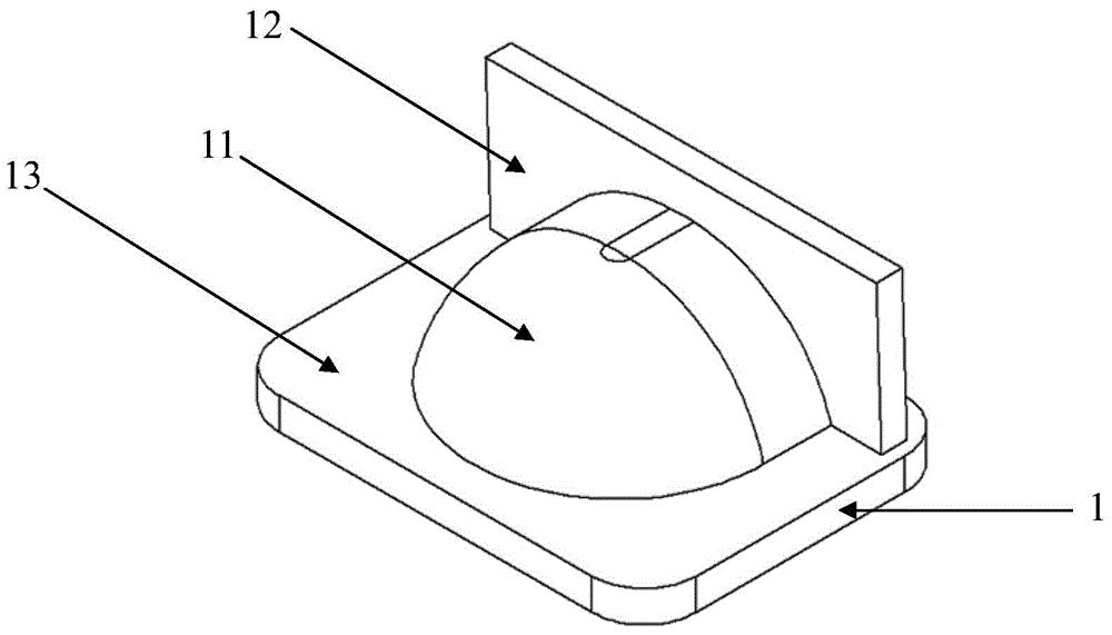
[0065] refer to figure 1 , figure 1 It is a schematic structural diagram of the LED lens provided by Embodiment 1 of the present invention; it can be seen from the figure that the LED lens 1 provided by Embodiment 1 of the present invention includes: astigmatism unit 11, reflection unit 12, base 13, astigmatism unit 11 and The reflection unit 12 is located above the base 13 and is an integrated structure.

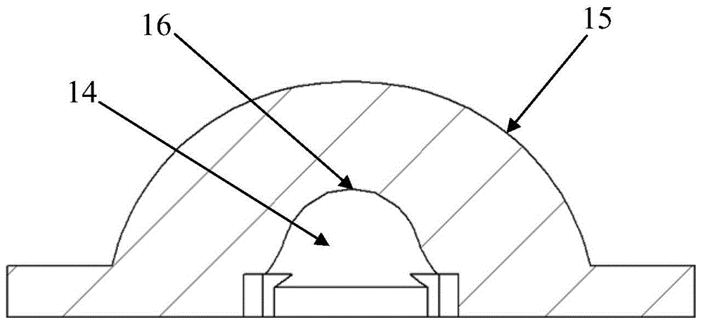
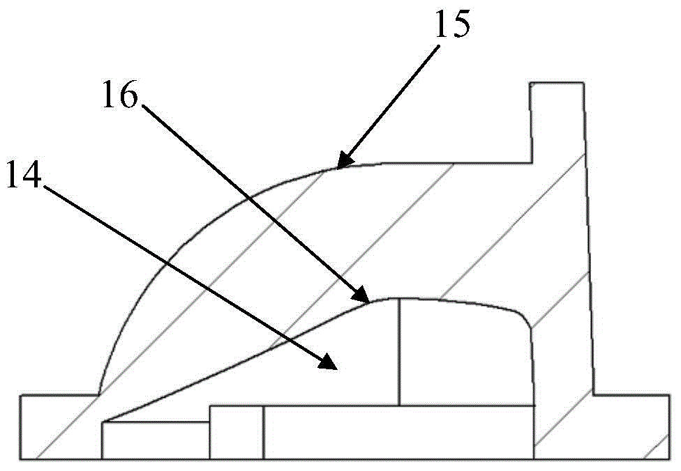
[0066] refer to figure 2 , image 3 , figure 2 The C0-180 sectional view of the LED lens provided by Embodiment 1 of the present invention, image 3 The C90-270 cross-sectional view of the LED lens provided for Embodiment 1 of the present invention; it can be seen from the figure that the LED lens 1 has an inner cavity 14, and the inner cavity 14 is surrounded by the astigmatism unit 11 and the base 13 of the LED lens 1, The surface of the inner cavity 14 is the inner surface 16 of the LED lens, including the inner surface of the astigmatism unit 11 and the inner sur...

Embodiment 2

[0069] refer to Figure 9 , Figure 9 Schematic diagram of the structure of the LED lens provided by Embodiment 2 of the present invention; it can be seen from the figure that the LED lens 1 provided by Embodiment 2 of the present invention includes: astigmatism unit 11, reflection unit 12, base 13, astigmatism unit 11 and The reflection unit 12 is located above the base 13 and is an integrated structure.

[0070] refer to Figure 10 , Figure 11 , Figure 10 The C0-180 cross-sectional view of the LED lens provided by Embodiment 2 of the present invention, Figure 11 The C90-270 cross-sectional view of the LED lens provided by the second embodiment of the present invention; it can be seen from the figure that the LED lens 1 has an inner cavity 14, and the inner cavity 14 is surrounded by the astigmatism unit 11 and the base 13 of the LED lens 1, The surface of the inner cavity 14 is the inner surface 16 of the LED lens, including the inner surface of the astigmatism unit ...

Embodiment 3

[0073] refer to Figure 16 , Figure 16 A schematic structural diagram of the LED lens provided by the third embodiment of the present invention; it can be seen from the figure that the LED lens 1 provided by the third embodiment of the present invention includes: an astigmatism unit 11, a reflection unit 12, a base 13, an astigmatism unit 11 and The reflection unit 12 is located above the base 13 and is an integrated structure.

[0074] refer to Figure 17 , Figure 18 , Figure 17 The C0-180 sectional view of the LED lens provided by Embodiment 3 of the present invention, Figure 18 The C90-270 cross-sectional view of the LED lens provided for the third embodiment of the present invention; it can be seen from the figure that the LED lens 1 has an inner cavity 14, and the inner cavity 14 is surrounded by the astigmatism unit 11 and the base 13 of the LED lens 1, The surface of the inner cavity 14 is the inner surface 16 of the LED lens, including the inner surface of the...


PUM


Abstract

The invention discloses an LED lens and a lens module thereof. The LED lens comprises a light scattering unit, a reflecting unit and a base, wherein the profile of the outer surface of the C0-180 section of the light scattering unit is hemispherical or similarly hemispherical; the profile of the inner surface of the C0-180 section of the light scattering unit is conical or similarly conical; the profiles of the outer surface and the inner surface of a C90-270 section of the light scattering unit are asymmetric; the reflecting unit is positioned on one side of the light scattering unit; the LED lens is provided with an inner cavity; the surface of the inner cavity is the inner surface of the LED lens; the vertex of the outer surface of the light scattering unit is vertically aligned with the vertex of the inner surface of the LED lens; and the LED lens module consists of a plurality of LED lenses. By the illumination function of the LED lens, asymmetric batwing light distribution applicable to street illumination can be realized, total reflection of the surface of the lens is effectively reduced, a plurality of light rays can exit at one step and illuminate the area of a road surface, and the use ratio on luminous flux of illumination can be increased.

Description

technical field [0001] The invention relates to the technical field of LED lighting, in particular to an LED lens and a lens module group thereof. Background technique [0002] LED is easy to achieve various forms of light distribution. A commonly used technical method is to design light distribution through secondary lenses, that is, to install an independent lens on the basis of a well-made LED single lamp to carry out light distribution design. The adopted The lens is generally made of polymethyl methacrylate (PMMA). This lens is independent of the LED single lamp and is called a secondary lens. The secondary lens and the LED single lamp together form an optical system to obtain the target light distribution form. . [0003] The C-plane system is a commonly used coordinate system for measuring and describing the spatial light intensity distribution of light sources or lamps. This system can be used in photometric testing of LED light sources or lamps. Measure and descri...

Claims


Application Information

Patent Timeline
Patent Type & Authority Patents(China)
IPC IPC(8): F21V5/04F21V13/02
Inventor 王慧东刘凯孙夕庆张彦伟孔瑞
Owner ADVANCED OPTRONIC DEVICES CHINA
Why Eureka
Try Eureka