Mixed refrigerant refrigeration circulating system

A technology of mixed working fluid and circulation system, which is applied in refrigerators, refrigeration and liquefaction, and irreversible cycle compressors, etc., can solve the problems of increasing the irreversible loss of the system, failing to achieve high-efficiency low-temperature refrigeration, reducing compressor efficiency, etc. The effect of power consumption, increasing back pressure, and increasing suction pressure

Active Publication Date: 2013-12-25
TECHNICAL INST OF PHYSICS & CHEMISTRY - CHINESE ACAD OF SCI
View PDF10 Cites 8 Cited by
  • Summary
  • Abstract
  • Description
  • Claims
  • Application Information

AI Technical Summary

Problems solved by technology

Under a certain refrigeration temperature requirement, when the ambient temperature is constant, increasing the exhaust pressure can improve the performance of the circulation system; however, the higher the pressure ratio of the compressor, the lower the efficiency of the compressor and increase the irreversible loss of the system
Therefore, in the refrigeration cycle system, it is impossible to achieve high-efficiency low-temperature refrigeration simply by increasing the discharge pressure of the compressor.

Method used


Image

  • Mixed refrigerant refrigeration circulating system
  • Mixed refrigerant refrigeration circulating system
  • Mixed refrigerant refrigeration circulating system

Examples


Embodiment 1

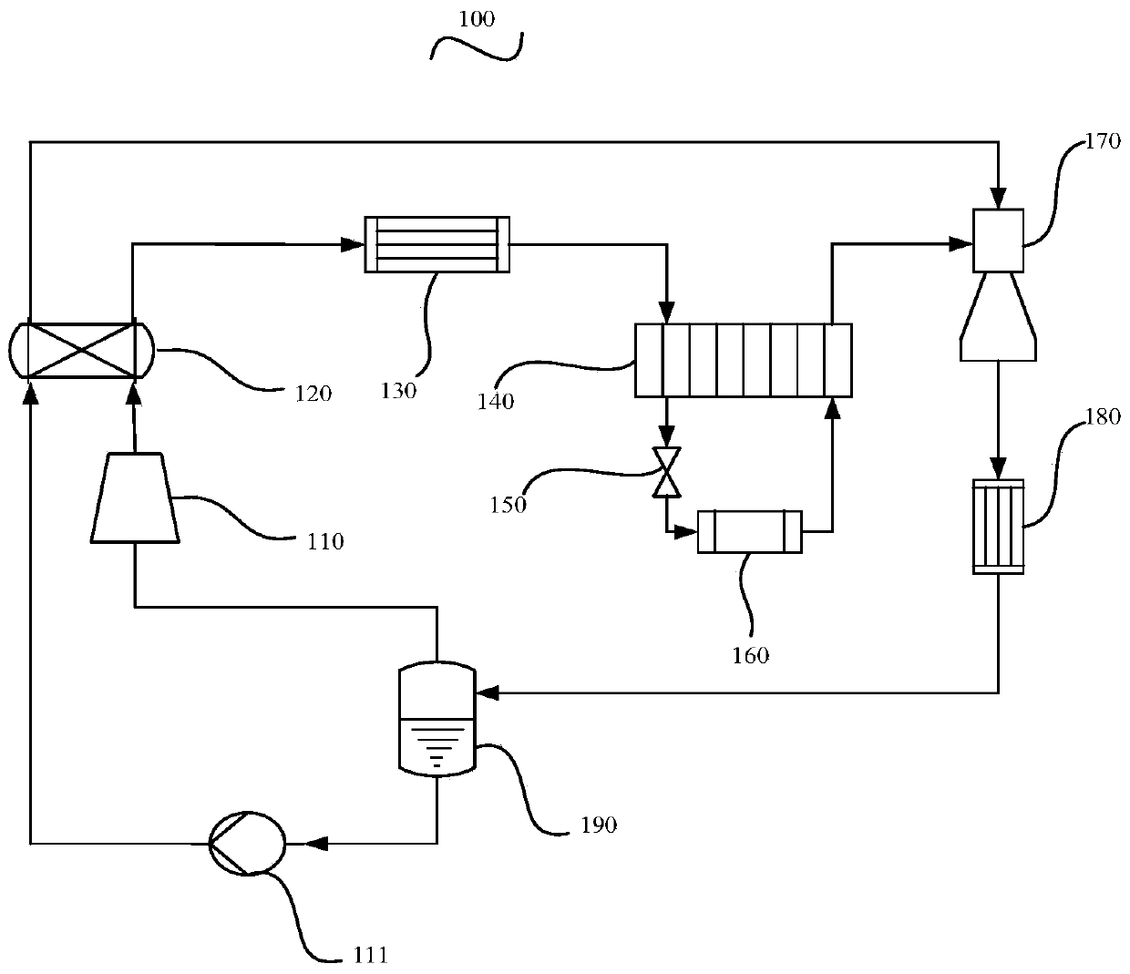
[0058] see Figure 1a , is a schematic structural diagram of a mixed working medium refrigeration cycle system provided in an embodiment of the present invention-a preferred embodiment. The mixed working medium refrigeration cycle system 100 includes: a compressor 110, a generator 120, a first condenser 130, a first Heat exchanger 140 , throttle valve 150 , evaporator 160 , ejector 170 , second condenser 180 , gas-liquid separator 190 and drive pump 111 .

[0059] Wherein, the high pressure outlet of the compressor 110 is connected to the heat exchange inlet of the generator 120, the heat exchange outlet of the generator 120 is connected to the inlet of the first condenser 130, and the outlet of the first condenser 130 is connected to the high pressure inlet of the first heat exchanger 140, The high-pressure outlet of the first heat exchanger 140 is connected to the inlet of the throttle valve 150, the outlet of the throttle valve 150 is connected to the inlet of the evaporator...

Embodiment 2

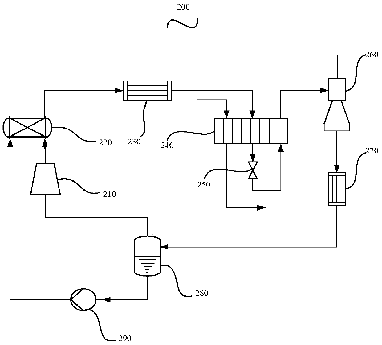
[0064] see Figure 2a , is a schematic structural diagram of a mixed working medium refrigeration cycle system provided in Embodiment 2 of the present invention. The mixed working medium refrigeration cycle system 200 includes a compressor 210, a generator 220, a first condenser 230, a second condenser Heater 240, throttle valve 250, ejector 260, second condenser 270, gas-liquid separator 280 and driving pump 290;

[0065] Wherein, the high pressure outlet of the compressor 210 is connected with the heat exchange inlet of the generator 220, the heat exchange outlet of the generator 220 is connected with the inlet of the first condenser 230, and the outlet of the first condenser 230 is connected with the first high pressure of the second heat exchanger 240. Inlet, the first high-pressure outlet of the second heat exchanger 240 is connected to the inlet of the throttle valve 250, the outlet of the throttle valve 250 is connected to the low-pressure inlet of the second heat excha...

Embodiment 3

[0071] see Figure 3a , is a schematic structural diagram of a mixed working medium refrigeration cycle system provided in Embodiment 3 of the present invention. The mixed working medium refrigeration cycle system 300 includes a compressor 310, a generator 320, a first condenser 330, a third condenser Heater 340, fourth heat exchanger 350, first throttle valve 360, evaporator 370, ejector 380, second condenser 390, gas-liquid separator 311, second throttle valve 312 and drive pump 313 ;

[0072] Wherein, the high pressure outlet of the compressor 310 is connected to the heat exchange inlet of the generator 320, the heat exchange outlet of the generator 320 is connected to the inlet of the first condenser 330, and the outlet of the first condenser 330 is connected to the high pressure inlet of the third heat exchanger 340, The high-pressure outlet of the third heat exchanger 340 is connected to the high-pressure inlet of the fourth heat exchanger 350, the high-pressure outlet ...


PUM


Abstract

The invention provides a mixed refrigerant refrigeration circulating system which comprises a compressor, a generator, a first condenser, a first heat exchanger, a throttling valve, an evaporator, an injector, a second condenser, a liquid-vapor separator and a driving pump. Mixed refrigerant passes the compressor to enter the generator, the condensers and the heat exchanger, and then enters the heat exchanger to be reheated prior to be injected by the injector; after being mixed with the injected refrigerant, the mixed refrigerant enters the condensers to turn into vapor and liquid phases, and after being separated via the liquid-vapor separator, the vapor-phase refrigerant enters the compressor; the liquid-phase refrigerant passes the driving pump and the generator, then flows into the injector prior to injecting the vapor-phase refrigerant reheated by the heat exchanger, and finally is mixed in the injector prior to entering condensers, and accordingly circulation is finished. The mixed refrigerant refrigeration circulating system has the advantages that the compressor is used for heat remove, high-temperature and high-pressure steam is generated to drive the injector to inject throttled refrigerant, suction pressure of the compressor is raised, back pressure is increased, and efficient low-temperature refrigeration is achieved.

Description

technical field [0001] The invention belongs to the technical field of low temperature and refrigeration, and relates to a refrigeration cycle system, in particular to a mixed working medium refrigeration cycle system. Background technique [0002] Mixed refrigerant throttling refrigeration technology was first proposed in the 1930s. Due to its excellent performance in the temperature range from 80K to 230K, it has gradually developed into the main refrigeration method in this wide temperature range. Especially since the 1970s, cryogenic mixed working fluid throttling technology has been more and more used in natural gas liquefaction, making this technology develop rapidly. In addition, the mixed working fluid throttling refrigeration technology can also be applied in some special fields, such as precooling of large hydrogen and helium refrigeration (liquefaction) systems, or providing low temperature precooling for other large systems. [0003] However, in the refrigeratio...

Claims


Application Information

Patent Timeline
Patent Type & Authority Applications(China)
IPC IPC(8): F25B1/00
Inventor 公茂琼吴剑峰邹鑫
Owner TECHNICAL INST OF PHYSICS & CHEMISTRY - CHINESE ACAD OF SCI
Why Eureka
Try Eureka