
Laser strapdown inertial navigation system prism ridge orientation installation error calibration method

A strapdown inertial navigation and installation error technology, which is applied in the field of strapdown inertial navigation systems, can solve the problems that the results are easily affected by the test equipment and the operation process, the installation error of the strapdown inertial group prism, and the increase in calibration costs, etc., to achieve reduction Calibration cost, convenient operation, and solve the effect of complex operation

Active Publication Date: 2013-12-25
HUNAN AEROSPACE ELECTROMECHANICAL EQUIP & SPECIAL MATERIAL INST
View PDF3 Cites 26 Cited by
  • Summary
  • Abstract
  • Description
  • Claims
  • Application Information

AI Technical Summary

Problems solved by technology

[0002] At present, the turntable calibration method is used to calibrate the installation error of the strapdown inertial group prism. Although the principle of this method is simple and the accuracy is high, it must be calibrated on a high-precision turntable, and the calibration cost increases.
[0003] For the laser strapdown inertial navigation system that uses the accelerometer coordinate system as the inertial navigation body coordinate system, the traditional prism calibration method cannot directly calibrate the azimuth installation error between the prism ridge line and the accelerometer coordinate system, and needs to go through the hexahedron coordinate system and the accelerometer coordinate system. Comprehensive calculation of accelerometer installation error under
The operation is very complex and the results are easily affected by the test equipment and operation process

Method used


Image

  • Laser strapdown inertial navigation system prism ridge orientation installation error calibration method
  • Laser strapdown inertial navigation system prism ridge orientation installation error calibration method

Examples


Embodiment Construction

[0017] Method of the present invention is as follows:

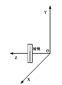
[0018] 1) Adjust the levelness of the marble slab or turntable to within 1″, install the laser strapdown inertial navigation system on a hexahedron box (the laser strapdown inertial navigation system itself has a positioning surface, and it can be placed stably), wipe the square Box (or laser strapdown inertial navigation system) positioning surface; can be according to figure 1 Place the laser strapdown inertial navigation system for the schematic diagram of the prism placement;

[0019] 2) Power on the laser strapdown inertial navigation system, set up the self-calibration value theodolite, make the height of the self-calibration value theodolite consistent with the prism height of the laser strapdown inertial navigation system, and make the self-calibration value theodolite aim at the laser strapdown inertial navigation system Prism;

[0020] 3) The self-alignment theodolite reads the pitch angle of the prism of the ...


PUM


Abstract

The invention discloses a laser strapdown inertial navigation system prism ridge orientation installation error calibration method. The method utilizes calibration equipment such as a marble flat plate or a rotary table and a self-alignment theodolite. Through integrated computation on an inertial navigation product accelerometer leveling angle and a self-alignment theodolite-aimed prism pitching angle, a prism ridge orientation installation error computational formula is derived. The method is simple and practicable, is convenient for operation, and solves the problem that the traditional calibration method for calibration of a laser strapdown inertial navigation system adopting an accelerometer coordinate system as an inertial navigation proprio-coordinate system has high calibration complexity. The method can realize direct calibration of a prism ridge orientation installation error of the laser strapdown inertial navigation system adopting the accelerometer coordinate system as the inertial navigation proprio-coordinate system so that prism orientation installation error calibration is fast.

Description

technical field [0001] The invention relates to a strapdown inertial navigation system, in particular to a method for calibrating the installation error of the prism ridge line azimuth of the laser strapdown inertial navigation system. Background technique [0002] At present, a turntable calibration method is used to calibrate the installation error of the strapdown inertial group prism. Although this method has a simple principle and high precision, it must be calibrated on a high-precision turntable, and the calibration cost increases. [0003] For the laser strapdown inertial navigation system that uses the accelerometer coordinate system as the inertial navigation body coordinate system, the traditional prism calibration method cannot directly calibrate the azimuth installation error between the prism ridge line and the accelerometer coordinate system, and needs to go through the hexahedron coordinate system and the accelerometer coordinate system. The comprehensive cal...

Claims


Application Information

Patent Timeline
IPC IPC(8): G01C25/00
Inventor 刘晓庆黄锡成李良君蔡铁鑫李仔冰
Owner HUNAN AEROSPACE ELECTROMECHANICAL EQUIP & SPECIAL MATERIAL INST
Learn More