Transmitting device for diaphragm gas meter

A membrane gas meter and driving device technology, which is applied in the direction of measuring devices, instruments, liquid/fluid solid measurement, etc., can solve problems such as disputes between gas companies and users, less counting, errors in counting and actual consumption, etc., and achieve stable and reliable signals output, simple structure effects

Active Publication Date: 2013-12-25
北京双得利科工贸有限责任公司
View PDF7 Cites 7 Cited by
  • Summary
  • Abstract
  • Description
  • Claims
  • Application Information

AI Technical Summary

Problems solved by technology

[0002] At present, with the rapid development of electronic technology, electronic technology and wireless networking transmission technology are widely used in gas meters, so that gas charges no longer need to check the meter at home, and the automatic emission of gas meter alarm signals saves manpower and material resources. The counting device currently uses electromagnetic or photoelectric counting technology. The electromagnetic type uses reed switch or Hall switch technology to set a permanent magnet on the driving wheel of the gas meter, and set a magnetic induction switch on the frame ( Hall switch, dry reed switch), the rotation of the wheel drives the permanent magnetic steel to drive the magnetic induction switch to output the counting signal to the counting controller, but this kind of signal d

Method used


Image

  • Transmitting device for diaphragm gas meter
  • Transmitting device for diaphragm gas meter
  • Transmitting device for diaphragm gas meter

Examples


Embodiment 1

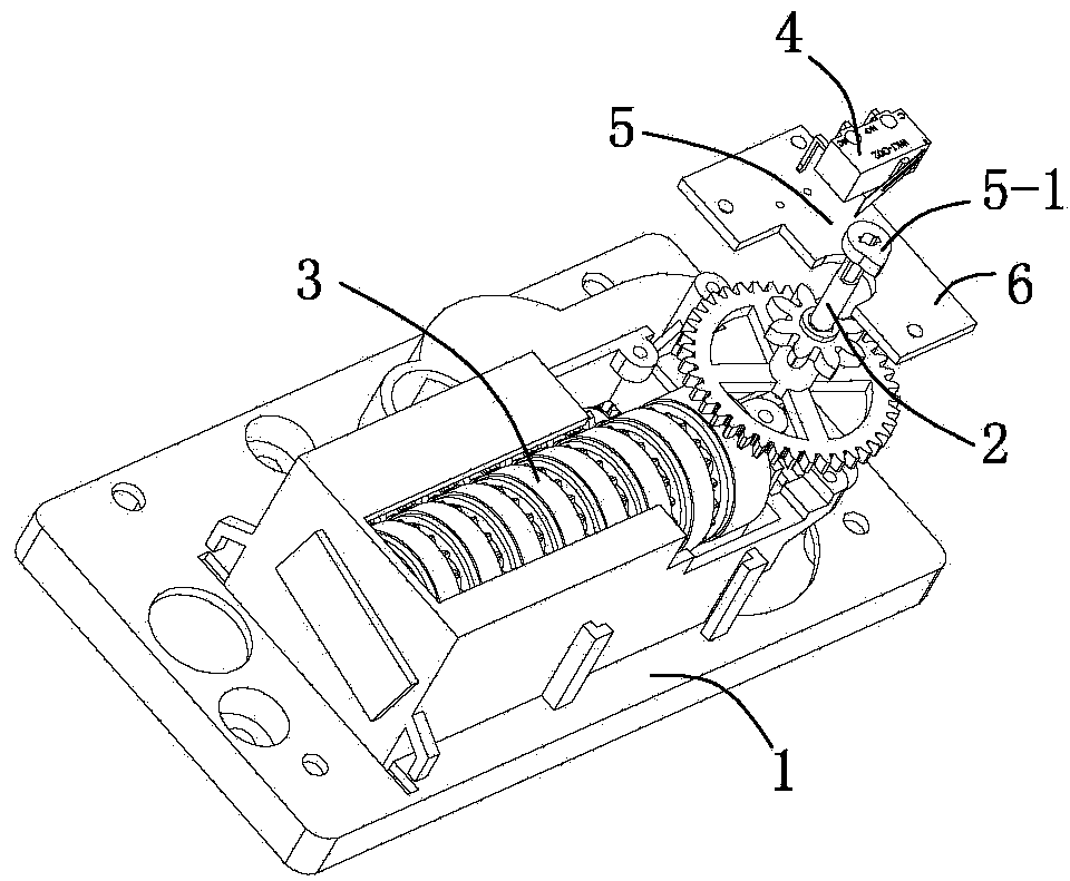
[0024] This embodiment is a preferred solution to the structure of the above-mentioned membrane gas meter signaling device: in the structure, as figure 1 As shown: the driving device is a cam 5-1, the cam is sleeved on the rotating shaft to rotate with the rotating shaft, and the protrusion of the cam pushes the contact of the micro switch to send an on-off counting signal.

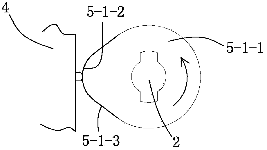
[0025] In the embodiment, such as figure 2 As shown, the protrusion of the cam is an arc-shaped protrusion 4-1-2 on the edge of the cam disc 5-1-1, and the arc-shaped protrusion is smoothly connected to the edge of the disc 5-1-3. The height is 1 / 3 to 1 / 2 of the radius of the disc.

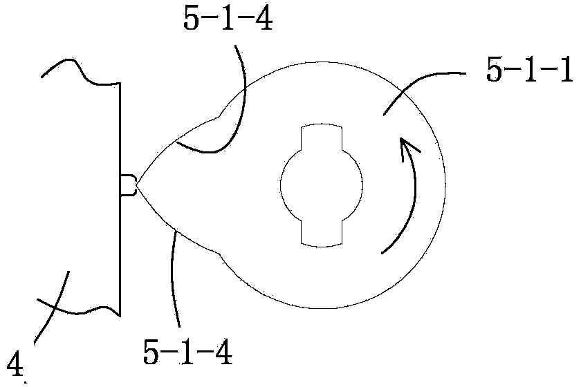
[0026] In the embodiment, the protrusion can also be another way, such as image 3 As shown: the protrusion is a protrusion formed by butting two arcs 5-1-4 symmetrical to the center of the cam disc, and the height of the protrusion is 1 / 3 to 1 / 2 of the radius of the cam disc.

[0027] In this embodiment, two arcs that are symmetri...

Embodiment 2

[0029] This embodiment is another preferred solution to the structure of the above-mentioned membrane gas meter signaling device: in the structure, as image 3 As shown, the driving device is a shaft sleeve 5-2. The shaft sleeve is sleeved on the shaft and is positioned radially without rotating with the shaft. The rotation of the shaft drives the shaft sleeve to move up and down to push the micro switch contacts to issue a count signal of on-off.

[0030] There are several ways to drive the shaft sleeve to move up and down:

[0031] One of the ways: such as Figure 4 Shown: the inner wall of the sleeve hole of the shaft sleeve is provided with a closed curved groove 5-2-1, and the rotating shaft is provided with a protrusion 2-1 matching the groove. When the rotating shaft rotates, the rotating shaft protrudes in the groove The rotary sliding drives the shaft sleeve to move up and down. The closed curve is a closed curve from rising to falling, and the rising angle of the curve is ...


PUM


Abstract

The invention discloses a transmitting device for a diaphragm gas meter. The transmitting device comprises a frame which is mounted on a diaphragm gas meter shell, wherein a rotating shaft and a mechanical counter are arranged on the frame; the rotating shaft is driven to rotate by gas flow; the mechanical counter is used for counting the flow of gas; a mechanical micro-switch is mounted on the frame; and a driving device is driven by the rotating shaft to drive a contact point of the micro-switch to transmit an on-off counting signal. The transmitting device for the diaphragm gas meter has a simple structure; the stable and reliable signal output of the gas meter can be realized by only additionally mounting the driving device and the micro-switch on the original rotating shaft, without changing an existing mechanical counter device of the gas meter; a cam and a shaft sleeve, as the driving device, are made of polytetrafluoroethylene plastics; the minimum resistance of the rotating shaft is brought by the special structure of the driving device; the usage count exceeds one million times; and after being tested, the transmitting device can meet the national standard of minimum measuring accuracy of the gas meter.

Description

Technical field [0001] The invention belongs to the technical field of gas meters, and in particular relates to a diaphragm gas meter signal transmitting device. The device is equipped with a cam on a transmission gear shaft, and a micro switch is used to stably trigger a micro switch to send a counting signal to realize the stability of the gas meter. Reliable signal output. Background technique [0002] At present, with the rapid development of electronic technology, gas meters have widely used electronic technology and wireless networking transmission technology, making gas charging no longer need to check the meter at home, and the automatic transmission of gas meter alarm signals, saving manpower and material resources. Counting devices currently use electromagnetic or photoelectric counting technology. The electromagnetic type uses reed tube or Hall switch technology to install a permanent magnet on the driving wheel of the gas meter, and install a magnetic induction switch...

Claims


Application Information

Patent Timeline
IPC IPC(8): G01F15/00G01F15/07
Inventor 彭明双刘伟成
Owner 北京双得利科工贸有限责任公司
Why Eureka
Try Eureka