Developing roller and developing box

A developing roller and developing cartridge technology, applied in the field of developing cartridges, can solve the problems of increased local friction in assembly or processing, deterioration of the developing roller body, and adhesion, etc., and achieve reduction of rotational torque and its fluctuations, reduction of frictional contact area, temperature evenly distributed effect

Active Publication Date: 2013-12-25
PRINT RITE UNICORN IMAGE PROD CO LTD
View PDF9 Cites 1 Cited by
  • Summary
  • Abstract
  • Description
  • Claims
  • Application Information

AI Technical Summary

Problems solved by technology

In order to achieve a sufficient sealing effect, the end of the developing roller must be in close contact with the felt and strongly squeeze or compress the entire seal, increasing the friction between the developing roller and the felt; thus, the rotational torque of the developing roller increases, It produces excess load on the developing roller, which affects its mechanical life; and increases the rotational torque of the entire developing cartridge, which affects the printing quality; during high-speed rotation, the friction between the seal and the contact part of the developing roller is large, and the heat generated by friction causes the developing roller to The temperature at both ends rises, which leads to the deterioration of the developing roller body, and causes the temperature distribution of the developing roller body along the axial direction to be uneven, resulting in different temperatures of the toner at different places, which affects the printing quality; especially for resin-type toner, the heat It is easy to soften the toner and cause adhesion, which affects the development and printing quality
[0005] For the long-term use of the developing cartridge, due to the long-term friction between the developing roller and the felt, the surface of the developing roller is unevenly worn and the friction between the two is increased. The above-mentioned problems caused by the increased friction are more obvious; in use, the developing Increased fluctuations in the rotational torque of the cartridge, affecting print quality and reducing the mechanical life of the developing roller
In addition, the local friction caused by errors such as assembly or processing increases, which makes the local temperature higher, which aggravates the adverse effects of the above problems
[0006] For a developing cartridge that has been printed continuously for a long time, due to the strong extrusion and rotating friction, the developing roller and the felt will generate a lot of heat, which will affect the actual sealing effect of the seal, resulting in powder leakage

Method used


Image

  • Developing roller and developing box
  • Developing roller and developing box
  • Developing roller and developing box

Examples


no. 1 example

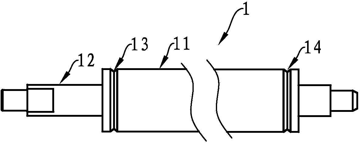
[0034] see figure 1 , figure 1 It is a structural schematic diagram of a developing roller according to the concept of the present invention. The developing roller 1 is composed of a developing roller body 11 and a developing roller shaft 12. The developing roller body 11 is sleeved outside the developing roller shaft 12. On the non-developing areas at both ends of the developing roller body 11, a circumferential concave groove 13 and Indented groove 14.

no. 2 example

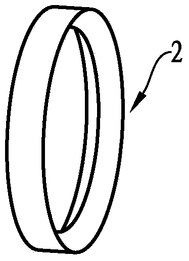
[0036] see figure 2 , figure 2 It is a structural schematic diagram of the collar in the second embodiment of the developing roller according to the concept of the present invention. Sleeve ring 2 is made of elastic wear-resistant material; Its structure can be a closed annular body with the same cross-section of the concave groove on the non-developing area at the two ends of the developing roller; Its structure is also It can be a strip whose cross section is the same as that of the concave groove on the non-developing area at both ends of the developing roller. One end of the strip is formed with a pin, and the other end is formed with a hole matched with the pin. Through the pin The fit with the hole constitutes as figure 2 The collar of the ring structure. The collar 2 can also be bonded by sealing felt or sealing sponge, etc. figure 2 The collar of the ring structure is shown.

[0037] The first embodiment of the developing cartridge

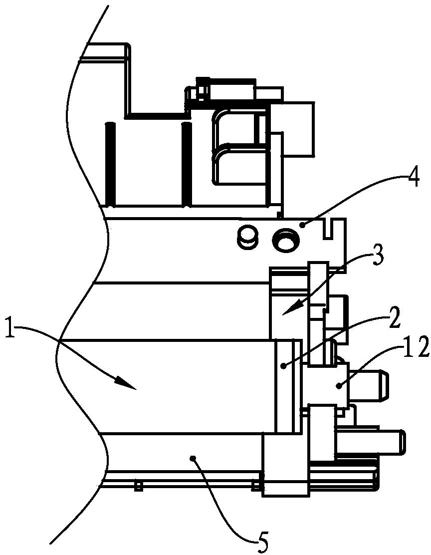
[0038] see image 3 , ...

no. 3 example

[0042] As the third embodiment of the developer cartridge according to the concept of the present invention, only the differences from the previous embodiment are described, and the semi-annular collar is used to replace the annular collar of the previous embodiment; The cross-section of the collar has the same part as the cross-section of the concave groove; the outer peripheral surface of the semi-circular collar is sealed with the corresponding box body of the developing cartridge by bonding or the like; the semi-circular collar and the concave The gap of the groove is filled with solid lubricant; the side of the semi-circular collar close to the developing area of ​​the developing roller is sealed with the end of the powder outlet knife and the sealing blade. The semi-circular ring, the concave groove and the corresponding box body of the developing cartridge together constitute a sealing system at the end of the developing roller.

[0043] The concept of the present inven...


PUM


Abstract

The invention relates to a developing roller for a laser printer, and particularly relates to a developing roller with small rotation torque and good end part sealing property. The developing roller comprises a developing roller body and a developing roller shaft, wherein the developing roller body is sleeved outside the developing roller shaft, and inwards-concave grooves matched with sealing members at end parts of the developing roller are respectively formed in non-developing regions at two ends of the developing roller body along the circumferential direction. The invention also provides a developing box comprising the developing roller. The developing box comprises a developing roller and sealing members, wherein the developing roller is rotatably supported on a developing roller bracket; inner circumferential surfaces of the sealing members are matched with the inwards-concave grooves in a sealing manner; outer circumferential surfaces of the sealing members are matched with two ends of the developing box in a sealing manner. Because the inwards-concave grooves matched with the sealing members at end parts of the developing roller are respectively formed in the non-developing regions at two ends of the developing roller body, the sealing property of two ends of the developing roller is better, the friction force between the developing roller and the sealing members is reduced, the rotation torque of the developing roller and the developing box is reduced, and the printing quality is improved.

Description

technical field [0001] The invention relates to parts of a laser printer, in particular to a developing roller for the laser printer and a developing box with good sealing performance and small rotational torque. Background technique [0002] Laser printer is currently one of the most widely used computer external output devices. It uses the physical and chemical principles of light, electricity, and heat to output text or images through interaction. The entire imaging process can be divided into charging, exposure, development, transfer, etc. Seven steps including printing, fixing, cleaning, and power elimination. [0003] In the above imaging process, the developing roller rotates to output the toner in the developing cartridge to the developing cartridge, because there is a gap between the end of the developing roller and the developing roller support on both ends of the developing cartridge, and the gap between the developing roller shaft and the developing roller suppor...

Claims


Application Information

Patent Timeline
Patent Type & Authority Applications(China)
IPC IPC(8): G03G15/08
Inventor 杨晓锋
Owner PRINT RITE UNICORN IMAGE PROD CO LTD
Why Eureka
Try Eureka