Distributed time sequence trigger control system

A technology of trigger control and timing controller, applied in electrical program control, comprehensive factory control, comprehensive factory control, etc., can solve the problems of strong electromagnetic interference, difficult wiring, complex structure, etc., to reduce electromagnetic interference, reduce The effect of wiring difficulty

Active Publication Date: 2013-12-25
HUAZHONG UNIV OF SCI & TECH
View PDF5 Cites 8 Cited by
  • Summary
  • Abstract
  • Description
  • Claims
  • Application Information

AI Technical Summary

Problems solved by technology

[0003] With the increase of device scale, various devices are distributed in different physical locations. Some large-scale physical experiment devices have already used a distributed system structure. If the timing trigger system still adopts the above-mentioned centralized structure, a large number of trigger signals will be transmitted one by one. To the subsystems in various places, the wiring is difficult, the cost is high, the system structure is complex, and the maintenance is difficult
[0004] At the same time, large-scale physical experiment devices often produce strong electromagnetic interference when conducting experiments
In the harsh electromagnetic environment of the site, the stability of the timing trigger system will be affected to a certain extent if the above-mentioned commercial general-purpose modular instruments are not specially designed for this environment.
Due to the complex structure of these instruments, unpredictable operation results are prone to occur after interference

Method used


Image

  • Distributed time sequence trigger control system
  • Distributed time sequence trigger control system
  • Distributed time sequence trigger control system

Examples


Embodiment Construction

[0016] In order to make the object, technical solution and advantages of the present invention clearer, the present invention will be further described in detail below in conjunction with the accompanying drawings and embodiments. It should be understood that the specific embodiments described here are only used to explain the present invention, not to limit the present invention. In addition, the technical features involved in the various embodiments of the present invention described below can be combined with each other as long as they do not constitute a conflict with each other.

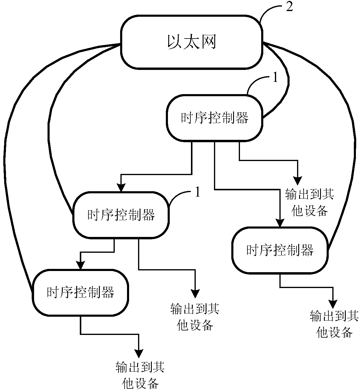
[0017] The distributed timing trigger control system provided by the embodiment of the present invention is mainly used to provide timing trigger and clock synchronization for large-scale experimental devices; Provide precise timing trigger and clock.

[0018] figure 1 The overall structure of the distributed timing trigger control system provided by the embodiment of the present invention is ...


PUM


Abstract

The invention discloses a distributed time sequence trigger control system. The system comprises a plurality of time sequence controllers and an optical fiber for connecting the time sequence controllers into a tree network, and further comprises a trigger input, a clock input and a sudden-stop input; all outputs of each time sequence controller can be used for providing clock or trigger for other equipments or connected with clock or trigger inputs of other time sequence controllers; by only using the time sequence trigger function, the trigger output of one node can be connected with the trigger input of another anode without connecting a clock signal when the accurate time synchronization is unnecessary. The distributed system structure is realized by adopting the tree network and the optical fiber, the influence of electromagnetic interference is reduced, and the wiring difficulty is reduced; the system can be used for providing time sequence trigger and clock signals with high precision for a large physical experiment device.

Description

technical field [0001] The invention belongs to the field of large-scale physical experiment devices, and more specifically relates to a distributed timing trigger control system. Background technique [0002] Large-scale physical experimental devices, such as large-scale linear accelerators and tokamak fusion experimental devices, all contain many subsystems and instruments, and need to accurately enter different operating states at different times. Therefore, a timing control system is needed to send trigger signals to other devices after the preset time in the program. At present, there is no timing trigger system specially used for large-scale physical experiment devices on the market. Many large-scale experimental devices use modular instruments, such as CPCI, PXI bus equipment and corresponding chassis controllers, and then cooperate with input and output interface modules to form a centralized timing trigger system. [0003] With the increase of device scale, variou...

Claims


Application Information

Patent Timeline
Patent Type & Authority Applications(China)
IPC IPC(8): G05B19/418
CPCY02P90/02
Inventor 张明郑玮赵青
Owner HUAZHONG UNIV OF SCI & TECH
Why Eureka
Try Eureka