
Split type integrated pressurized water reactor hanging under the hanging basket

A split-type, pressurized water reactor technology, applied in the direction of moderator/core structure, reactor, greenhouse gas reduction, etc., can solve the problems of inconvenient installation, difficult installation and disassembly, complicated installation structure, etc. Disassembly, easy in-service inspection, reduction in axial dimension

Active Publication Date: 2016-08-10
NUCLEAR POWER INSTITUTE OF CHINA
View PDF10 Cites 0 Cited by
  • Summary
  • Abstract
  • Description
  • Claims
  • Application Information

AI Technical Summary

Problems solved by technology

[0002] In the prior art, the length of the hanging basket is long, the installation is inconvenient, the limit is not accurate, and the installation and disassembly are very difficult; the compression component is relatively long in design, and it is also difficult to install and disassemble. At the same time, the installation structure of the two parts is complicated and reliable. In addition, the flow channel for coolant diversion is double-layer sleeve type flow channel at home and abroad. The structure of the flow channel is complex, maintenance and replacement are difficult, and it affects the in-service inspection of pressure vessels.
Since the double-layer casing is close to the main pump and is connected with dissimilar metals, the reliability of the double-layer casing is affected, and once an accident occurs, it is difficult to repair

Method used


Image

  • Split type integrated pressurized water reactor hanging under the hanging basket
  • Split type integrated pressurized water reactor hanging under the hanging basket

Examples


Embodiment Construction

[0025] The present invention will be described in detail below in conjunction with the accompanying drawings and specific embodiments.

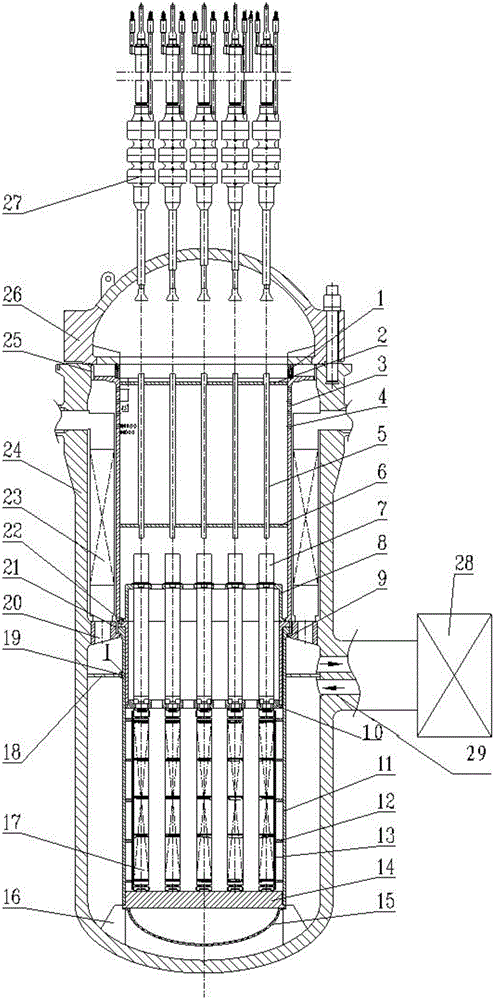
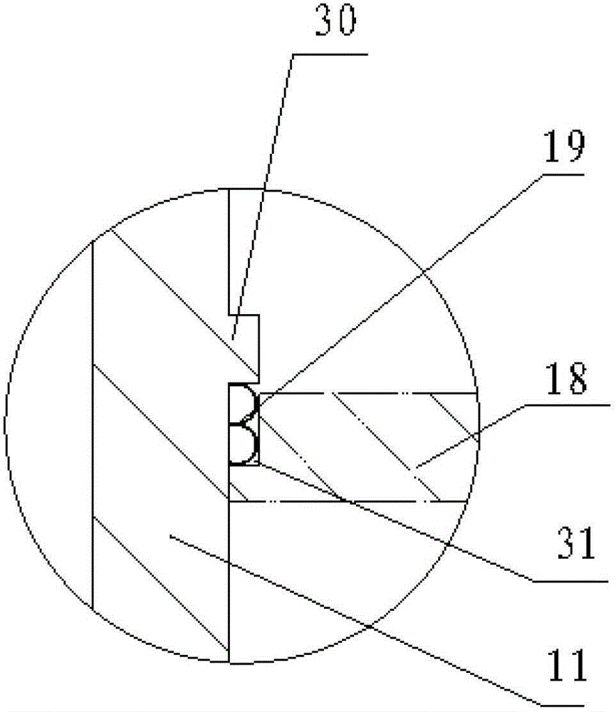
[0026] Such as figure 1 As shown, the radial limit block 16 is welded at the bottom of the pressure vessel cylinder 24, and the inner wall of the pressure vessel cylinder 24 is processed with a ring-shaped hanging basket supporting step 20, and the hanging basket assembly is located under the pressure of the hanging basket supporting step 20. At the bottom of the container cylinder 24, the above-mentioned radial limit block 16 can limit the radial movement of the hanging basket assembly. Weld the flow shunt cover 15 under the hanging basket assembly. A fuel assembly 17 is installed at the bottom of the hanging basket assembly, a pressing assembly is fixedly installed on the hanging basket assembly, and a guide assembly 7 is fixedly installed on the pressing assembly. Above the compression assembly is a compression cylinder assembly, and a s...


PUM


Abstract

The invention relates to the technical field of nuclear power integral reactors and particularly discloses a split-type integral pressurized water reactor with a down-suspended basket. The split-type integral pressurized water reactor comprises a pressure container cylinder, wherein a pressure container top cover is arranged on the pressure container cylinder, the side face of the pressure container cylinder is connected with a main coolant pump, a down-suspended basket component and an impaction component are arranged inside the pressure container cylinder, the impaction component is positioned above the down-suspended basket component, a fuel component is arranged in the down-suspended basket component, a flow shunting cover is arranged below the down-suspended basket component, a guide Component is in the impaction component, a control rod driving mechanism fixed on the pressure container top cover is positioned above the impaction component, and the control rod driving mechanism is fixed on the pressure container top cover. By virtue of integrated double-flow holes on the side face of a pressure container, coolant inlet and outlet structures of a main pump and the pressure container are simplified to facilitate the in-service inspection of welding seams of the pressure container. The down-suspended basket structure is mounted at the middle lower part of the pressure container cylinder, so that the axial dimension is greatly reduced, the axial dimension of the impaction component is correspondingly reduced, the whole structure is simplified, the reliability is improved, and the mounting and dismounting are convenient.

Description

technical field [0001] The invention belongs to the technical field of nuclear power integrated reactors, and in particular relates to an integrated pressurized water reactor. Background technique [0002] In the prior art, the length of the hanging basket is long, the installation is inconvenient, the limit is not accurate, and the installation and disassembly are very difficult; the compression component is relatively long in design, and it is also difficult to install and disassemble. At the same time, the installation structure of the two parts is complicated and reliable. In addition, the flow channel for coolant diversion is double-layer sleeve type flow channel at home and abroad. The structure of the flow channel is complex, maintenance and replacement are difficult, and it affects the in-service inspection of pressure vessels. Since the double-layer casing is close to the main pump and is connected by dissimilar metals, the reliability of the double-layer casing is ...

Claims


Application Information

Patent Timeline
Patent Type & Authority Patents(China)
IPC IPC(8): G21C13/02G21C13/024G21C13/028G21C5/02G21C5/06
CPCY02E30/30
Inventor 郝维明许斌张宏亮陈训刚罗英王留兵杜华夏欣
Owner NUCLEAR POWER INSTITUTE OF CHINA
Learn More