
Four-frequency plane microstrip antenna with miniaturized microwave absorption structure

A planar microstrip antenna and wave structure technology, applied in the direction of antenna, antenna grounding device, radiating element structure, etc., can solve the problems of limited electromagnetic wave radiation efficiency, large size of microstrip antenna, poor gathering and collecting effect, etc. Collection effect, the effect of enhancing radiation efficiency

Inactive Publication Date: 2013-12-25
CHANGCHUN INST OF OPTICS FINE MECHANICS & PHYSICS CHINESE ACAD OF SCI
View PDF7 Cites 2 Cited by
  • Summary
  • Abstract
  • Description
  • Claims
  • Application Information

AI Technical Summary

Problems solved by technology

[0006] In order to solve the technical problems in the prior art that the microstrip antenna has a large volume, poor gathering and collection effect, limited radiation efficiency for electromagnetic waves in a specific frequency band, and is not suitable for multiple frequency bands, the present invention provides a four-frequency planar microstrip with a miniaturized wave-absorbing structure antenna

Method used


Image

  • Four-frequency plane microstrip antenna with miniaturized microwave absorption structure
  • Four-frequency plane microstrip antenna with miniaturized microwave absorption structure
  • Four-frequency plane microstrip antenna with miniaturized microwave absorption structure

Examples


Embodiment Construction

[0032] The present invention will be further described in detail below in conjunction with the drawings.

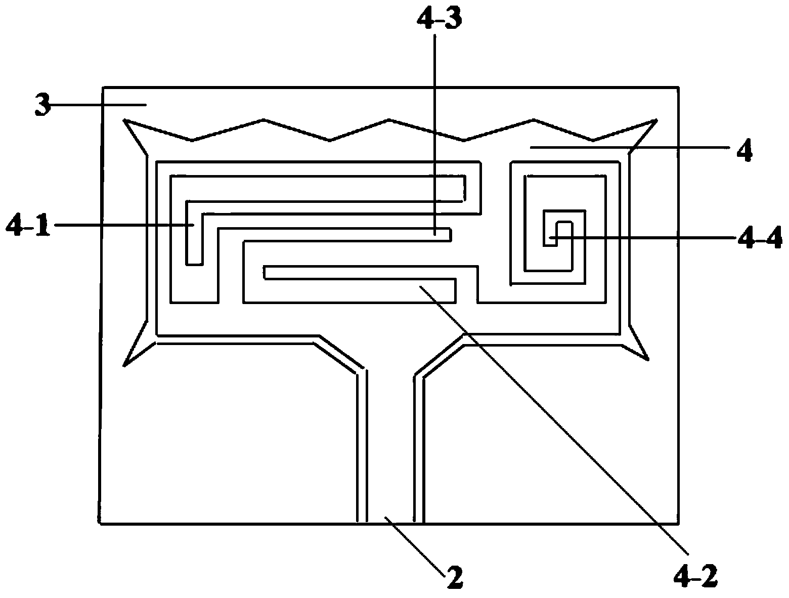
[0033] Such as figure 1 with figure 2 As shown, the miniaturized wave-absorbing structure of the four-frequency planar microstrip antenna of the present invention adopts a coplanar waveguide structure for feeding, and realizes the design concept of miniaturization and planarization of the antenna. It is mainly composed of a dielectric substrate 1, a feed line 2, and a ground plate. 3 and four-segment radiating unit 4, wherein the feeder 2, the ground plate 3 and the radiating unit 4 are all conductively arranged on the dielectric substrate 1, and are on the same plane with the same thickness of each part; the feeder 2 is conductive The lower end of the metal feeder cable is connected with a coaxial cable to receive electromagnetic waves; the four-segment radiating unit 4 is a conductive metal radiating unit, and the upper end is four resonant stubs that match electromagnetic...


PUM


Abstract

The invention discloses a four-frequency plane microstrip antenna with a miniaturized microwave absorption structure. The four-frequency plane microstrip antenna with the miniaturized microwave absorption structure solves the problems that a microstrip antenna is large in size, poor in gathering collection effect and not suitable for multiple frequency bands in the prior art. The antenna comprises a dielectric substrate, a feeder wire, a four-branch radiating unit and grounding plates, wherein the feeder wire is arranged on the upper surface of the dielectric substrate and is used for receiving electromagnetic waves, the four-branch radiating element is connected with the feeder wire and is used for radiating electromagnetic waves, and the grounding plates are arranged on the upper surface of the dielectric substrate and are symmetrical about the feeder wire in a left-right mode. The feeder wire and the four-branch radiating unit are arranged in an outline formed by the inner edges of the grounding plates, the inner edges of the grounding plates at the left side and the right side of the four-branch radiating unit are of a symmetrical trapezoidal structure, the inner edges of the grounding plates at the lower side of the four-branch radiating unit are of the structure of two trapezoids which are symmetrical about the feeder wire, the inner edges of the grounding plates at the upper side of the four-branch radiating unit are of the structure of a plurality of continuous triangles, and the inner edges of the grounding plates at the left side and the right side of the feeder wire are of the structure of parallel straight lines. The miniaturized microwave absorption four-frequency microstrip antenna is small in size, concentrated in energy and capable of achieving omnidirectional radiation to four frequency bands.

Description

Technical field [0001] The invention relates to the technical field of wireless communication, in particular to a miniaturized quad-frequency planar microstrip antenna with a wave-absorbing structure. Background technique [0002] A microstrip antenna is on a thin dielectric substrate, one side is attached with a thin metal layer as a grounding plate, and the other side is made into a metal patch with a certain shape by photolithography etching method, using microstrip line or coaxial probe An antenna formed by feeding the patch. Microstrip antennas have the advantages of miniaturization, easy integration, and good directivity, and have been widely used in wireless communication technology. [0003] Commonly used communication frequency bands for wireless communication systems are RFID system (2.4GHz, 5.8GHz), IEEE802.11b / g (2.4GHz), IEEE802.11a (5.2GHz), WIMAX (3.3-3.7GHz) and WLAN (2.45GHz, 5.15- 5.85GHz). [0004] The earliest microstrip antenna is only suitable for one communi...

Claims


Application Information

Patent Timeline
Patent Type & Authority Applications(China)
IPC IPC(8): H01Q1/48H01Q1/50H01Q1/38H01Q5/01H01Q17/00H01Q5/10
Inventor 汤洋高劲松王岩松梁凤超徐念喜陈新
Owner CHANGCHUN INST OF OPTICS FINE MECHANICS & PHYSICS CHINESE ACAD OF SCI
Learn More