Method for generating radio frequency orbital angular momentum beams based on annular traveling wave antenna
A technology of orbital angular momentum and traveling wave antennas, which is applied in loop antennas, antennas, electrical components, etc., to achieve the effects of easy implementation, increased capacity, and practical application
- Summary
- Abstract
- Description
- Claims
- Application Information
AI Technical Summary
Problems solved by technology
Method used
Image

Examples
Embodiment Construction
[0018] Below in conjunction with accompanying drawing, the present invention is described in further detail:
[0019] 1. Generation of radio frequency OAM beams based on ring traveling wave antennas.
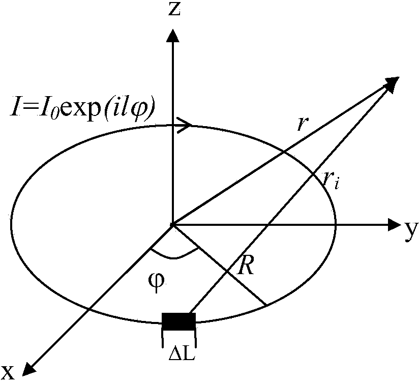
[0020] Assume that the loop traveling wave antenna is an electrical source antenna, such as figure 1 As shown, the current distribution on the antenna satisfies , calculate the radiation field of the loop traveling wave antenna in space.
[0021] The basic idea is: divide the circular antenna into N sections, and ensure that the length of each small section of antenna ΔL<<wavelength λ, because the current amplitude on the small section of antenna is the same, and the phase can also be regarded as the same, then the small antenna can be used as a galvanic couple pole, its far-field radiation in space can be calculated by the far-field radiation formula of the electric dipole antenna, as follows:
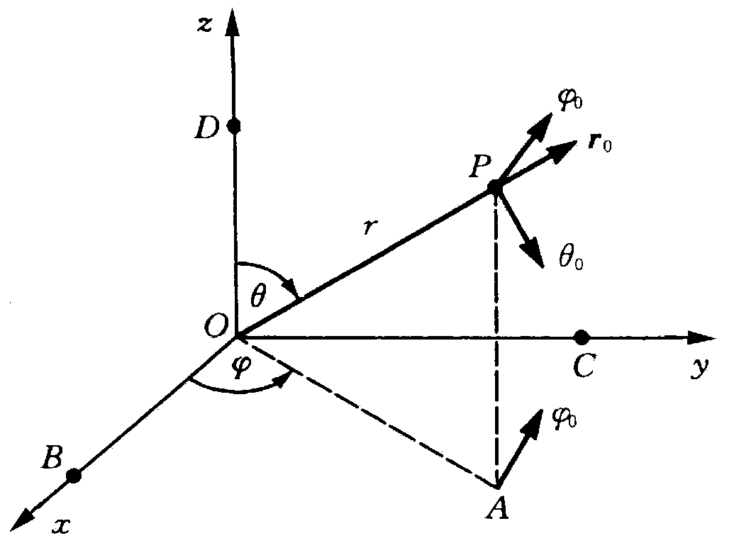
[0022] E = θ 0 ...
PUM
 Abstract
Description
Claims
Application Information
 - Generate Ideas
- Intellectual Property
- Life Sciences
- Materials
- Tech Scout
- Unparalleled Data Quality
- Higher Quality Content
- 60% Fewer Hallucinations
Browse by: Latest US Patents, China's latest patents, Technical Efficacy Thesaurus, Application Domain, Technology Topic, Popular Technical Reports.
© 2025 PatSnap. All rights reserved.Legal|Privacy policy|Modern Slavery Act Transparency Statement|Sitemap|About US| Contact US: help@patsnap.com