Linear rotation permanent magnet motor

A permanent magnet motor and linear technology, applied in the direction of electrical components, electromechanical devices, etc., can solve the problems of large number of winding phases, difficult processing, difficult control, etc., and achieve the effects of good heat dissipation conditions, reduced volume, and simple structure

Inactive Publication Date: 2013-12-25
SOUTHEAST UNIV
View PDF5 Cites 25 Cited by
  • Summary
  • Abstract
  • Description
  • Claims
  • Application Information

AI Technical Summary

Problems solved by technology

[0005] 3) The cross-coupling of the rotating magnetic field and the traveling wave magnetic field is not conducive to the optimal design of the motor;
[0006] 4) The integrated structure often adopts concentrated winding, and the number of winding phases is large, the control is difficult and the control strategy is complicated;
[0007] 5) The structure of the stator and the mover is special, the manufacturing process of the motor is complicated, and the processing is difficult;
[0008] 6) The control theory and technology of the linear rotation two-degree-of-freedom motor need to be improved

Method used


Image

  • Linear rotation permanent magnet motor
  • Linear rotation permanent magnet motor
  • Linear rotation permanent magnet motor

Examples


specific Embodiment approach 1

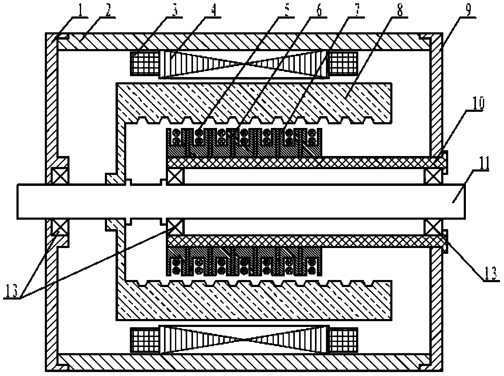
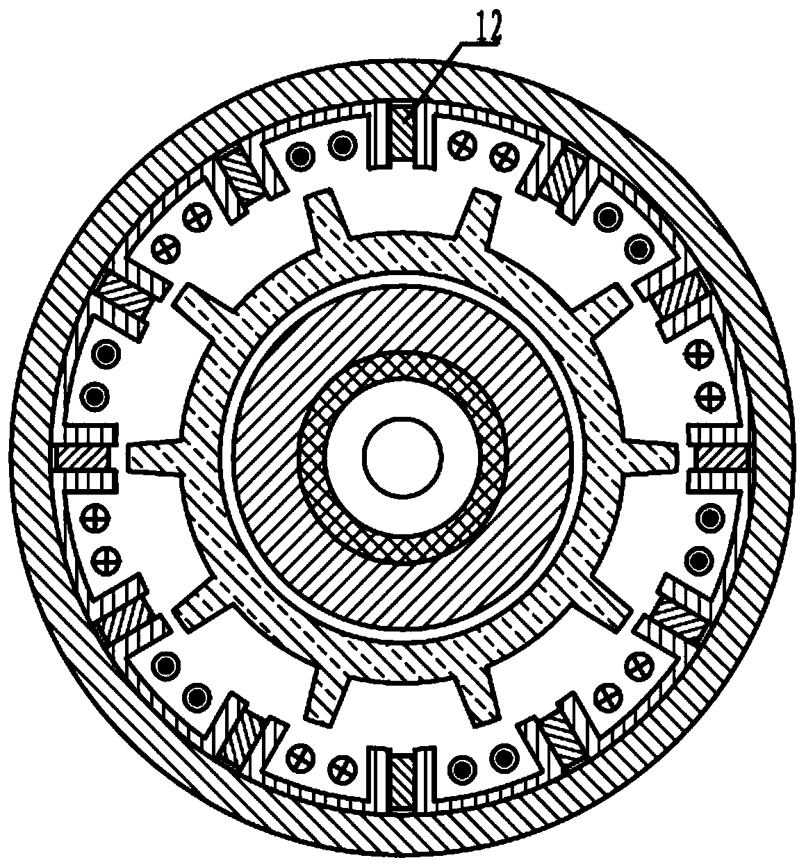
[0063] Specific embodiment one: the following combination figure 1 and figure 2 Describe this embodiment, the outer stator core 4 of the motor described in this embodiment, the outer stator winding 3, the outer stator permanent magnet 12 and the mover 8 constitute a rotary drive unit, the inner stator core 7, the inner stator winding 5, the inner stator permanent magnet 6 and mover 8 form a linear drive unit. The rotary drive unit adopts an inner rotor rotary motor structure, and the linear drive unit adopts a cylindrical linear motor structure.

[0064] The outer stator core 4 is formed by laminating a plurality of "U"-shaped punches along the axial direction, and then assembled along the circumferential direction. Along the circumferential direction, outer stator permanent magnets 12 are placed between the outer stator cores 4 .

[0065] The outer stator permanent magnets 12 are magnetized along the circumferential direction, and the magnetization directions of adjacent o...

specific Embodiment approach 2

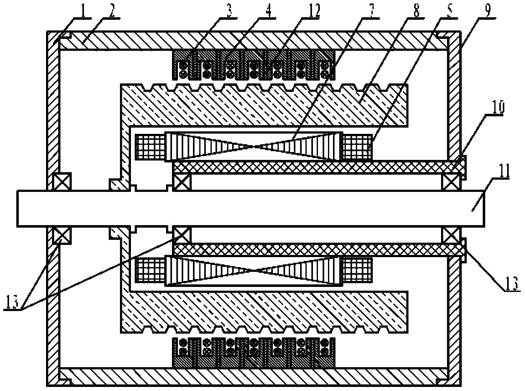
[0076] Specific embodiment two: the following combination image 3 and Figure 4 Describe this embodiment, the outer stator core 4 of the motor described in this embodiment, the outer stator winding 3, the outer stator permanent magnet 12 and the mover 8 constitute a linear drive unit, the inner stator core 7, the inner stator winding 5, the inner stator permanent magnet 6 and mover 8 constitute a rotary drive unit. The linear drive unit adopts a cylindrical linear motor structure, and the rotary drive unit adopts an outer rotor rotary motor structure.

[0077] The outer stator core 4 is formed by stacking a plurality of "U"-shaped punches along the circumferential direction, and then assembled along the axial direction. Along the axial direction, an outer stator permanent magnet 12 is placed between each outer stator core 4 .

[0078] The outer stator permanent magnets 12 are ring-shaped and magnetized along the axial direction, and the magnetization directions of adjacent ...


PUM


Abstract

The invention discloses a linear rotation permanent magnet motor. The linear rotation permanent magnet motor comprises an inner stator, an outer stator, a rotor located between the inner stator and the outer stator, a left end cover (1), a machine shell (2), an outer stator winding (3), an outer stator iron core (4) with a groove, an inner stator winding (5), an inner stator permanent magnet (6), an inner stator iron core (7) with a groove, a rotor (8), a right end cover (9), an inner stator support (10), a rotation shaft (11), an outer stator permanent magnet (12) and a bearing (13), wherein the left end cover (1), the machine shell (2) and the right end cover (9) form a cavity, the inner stator support (10) is arranged in the cavity, and one end of the inner stator support (10) is connected with the right end cover (9). According to the linear rotation permanent magnet motor, the structure of the linear rotation two-freedom-degree motor is simplified, the size and the weight of the motor are reduced, magnetic coupling of linear and rotary motion units is eliminated, and the control difficulty of linear and rotary motions is lowered.

Description

technical field [0001] The invention relates to a linear rotary permanent magnet motor, which is suitable for linear, rotary and helical drive occasions, and belongs to the technical field of motors. Background technique [0002] As far as the current motor motion control is concerned, most of them are single-degree-of-freedom motors, which can only perform linear motion or rotary motion. With the increase in the complexity of industrial drive systems and the improvement of drive precision requirements, one-dimensional motion single-degree-of-freedom motors cannot meet the drive requirements, and a large number of multi-dimensional motion motors and their drive mechanisms are required. Compared with single-degree-of-freedom motors, multi-degree-of-freedom motors not only have the characteristics of multi-dimensional motion, but also have higher mechanical integration, higher material utilization and flexible control characteristics. Linear rotary motion motor is a kind of m...

Claims


Application Information

Patent Timeline
Patent Type & Authority Applications(China)
IPC IPC(8): H02K16/04
Inventor 付兴贺李红艳林明耀
Owner SOUTHEAST UNIV
Why Eureka
Try Eureka