

Control method of permanent magnet synchronous brushless direct-current motor in low frequency
A brushless DC motor and permanent magnet synchronous technology, applied in motor generator control, electronic commutation motor control, control system, etc., can solve problems such as inaccurate estimation of shaft error and out-of-step detection of compressor position
- Summary
- Abstract
- Description
- Claims
- Application Information
AI Technical Summary
Problems solved by technology
Method used
Image

Examples
Embodiment
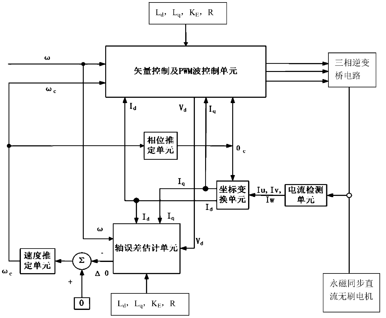
[0061] In this example, the permanent magnet synchronous brushless DC motor low frequency control system, such as figure 1 As shown, the permanent magnet synchronous DC brushless motor is respectively connected with the three-phase inverter bridge control circuit and the current detection unit, the current detection unit is connected with the coordinate transformation unit, and the coordinate transformation unit is respectively connected with the axis error estimation unit, the phase estimation unit and the vector control unit and the DC motor pulse width modulation PWM wave control unit, the axis error estimation unit is respectively connected with the speed estimation unit and the vector control and DC motor pulse width modulation PWM wave control unit, and the speed estimation unit is respectively connected with the phase estimation unit and the vector control and DC motor The pulse width modulation PWM wave control unit is connected, and the vector control and DC motor puls...
PUM
 Abstract
Description
Claims
Application Information