Variable orientation illumination-pattern rotator

An illumination mode, rotator technology, applied in the field of fluorescence microscopy

Active Publication Date: 2013-12-25
莱卡微系统 CMS +1
View PDF10 Cites 6 Cited by
  • Summary
  • Abstract
  • Description
  • Claims
  • Application Information

AI Technical Summary

Problems solved by technology

Laser exposure can span 5-100ms, camera readout can span about 50ms per full frame, grating motion and placement can span tens of millise

Method used


Image

  • Variable orientation illumination-pattern rotator
  • Variable orientation illumination-pattern rotator
  • Variable orientation illumination-pattern rotator

Examples


Embodiment Construction

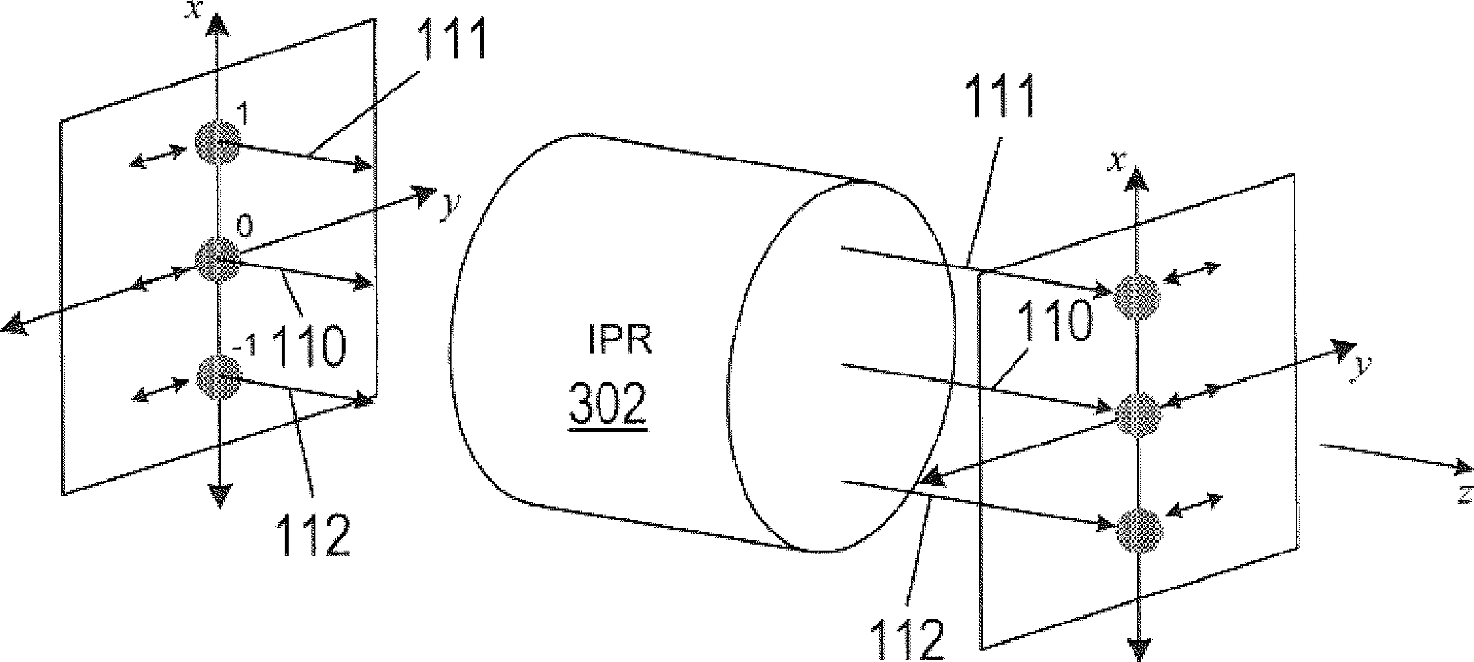
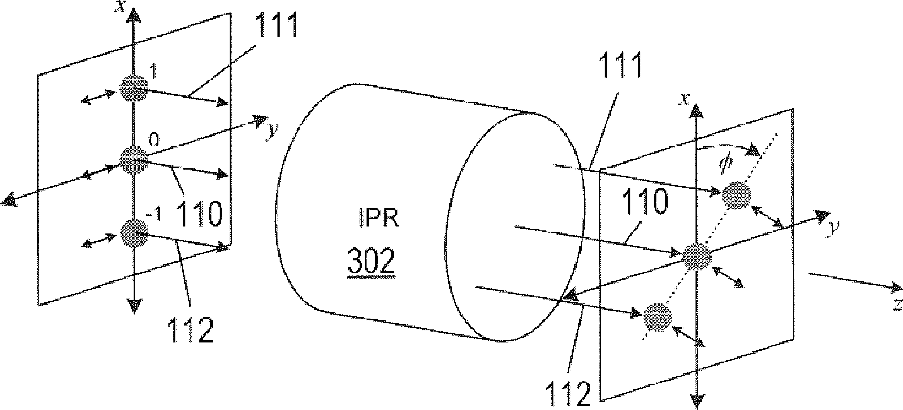
[0015] In a constructed illumination microscope ("SIM"), an interference pattern is projected onto the specimen and rotated. To generate a high-contrast interference pattern, the polarization of the beam forming the interference pattern is also rotated to match the rotation angle of the interference pattern. A variable orientation illumination pattern rotator ("IPR") is disclosed that can be used to rapidly rotate an interferometric pattern and rotate polarization to match the rotation angle of the interferometric pattern.

[0016] figure 1 A schematic representation of a conventional SIM instrument 100 is shown. Coherent light is output from a light source 102 (eg, a laser) and transmitted through a lens 104 and a polarizing plate 106 . The lens 104 collimates the light into a beam, and the polarizing plate 106 transmits only light of a particular polarization while blocking other polarizations. The polarized beam output from the polarizing plate 106 passes through a one-...


PUM


Abstract

Variable orientation illumination-pattern rotators ("IPRs") that can be incorporated into structured illumination microscopy instruments to rapidly rotate an interference pattern are disclosed. An IPR includes a rotation selector and at least one mirror cluster. The rotation selector directs beams of light into each one of the mirror clusters for a brief period of time. Each mirror cluster imparts a particular predetermined angle of rotation on the beams. As a result, the beams output from the IPR are rotated through each of the rotation angles imparted by each of the mirror clusters. The rotation selector enables the IPR to rotate the beams through each predetermined rotation angle on the order of 5 milliseconds or faster.

Description

[0001] Cross References to Related Applications [0002] This application claims the benefit of US Provisional Patent Application No. 61 / 447,708, filed March 1, 2011; the disclosure of which is hereby incorporated by reference in its entirety. technical field [0003] The present disclosure relates to fluorescence microscopy, and in particular to a system for changing the orientation of an interference fringe pattern used to illuminate a specimen. Background technique [0004] Three-dimensional structured illumination microscopy ("3D-SIM") achieves a 1 / 2 improvement in lateral and axial resolution compared to conventional widefield fluorescence microscopy used in cell biology. Unlike some competing super-resolution techniques, 3D-SIM does not require specialized fluorescent dyes or proteins. Biologists use 3D-SIM to achieve high resolution but retain the convenience and familiarity of fluorescent labeling. Use shift and rotate lighting modes to make multiple images of obje...

Claims


Application Information

Patent Timeline
IPC IPC(8): G02B21/00
CPCG02B21/06G02B21/0032G02B21/082G02B21/16G02B21/367G02B27/58
Inventor J.R.库珀
Owner 莱卡微系统 CMS
Why Eureka
Try Eureka