U-shaped pipe landing leg punching tool
A U-shaped tube and punching technology, applied in the field of fixtures, can solve problems such as height difference, and achieve the effects of convenient use, simple structure, good technology and economic value
- Summary
- Abstract
- Description
- Claims
- Application Information
AI Technical Summary
Problems solved by technology
Method used
Image

Examples
Embodiment Construction
[0028] Below in conjunction with accompanying drawing and embodiment the present invention will be further described:
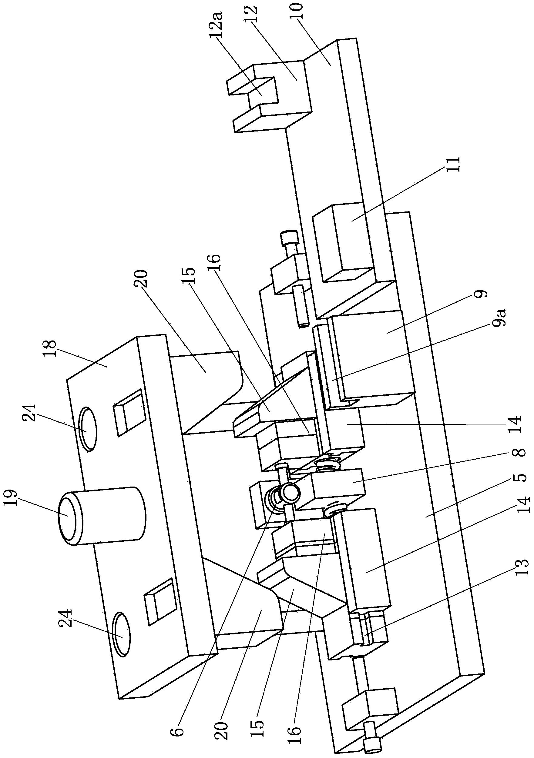
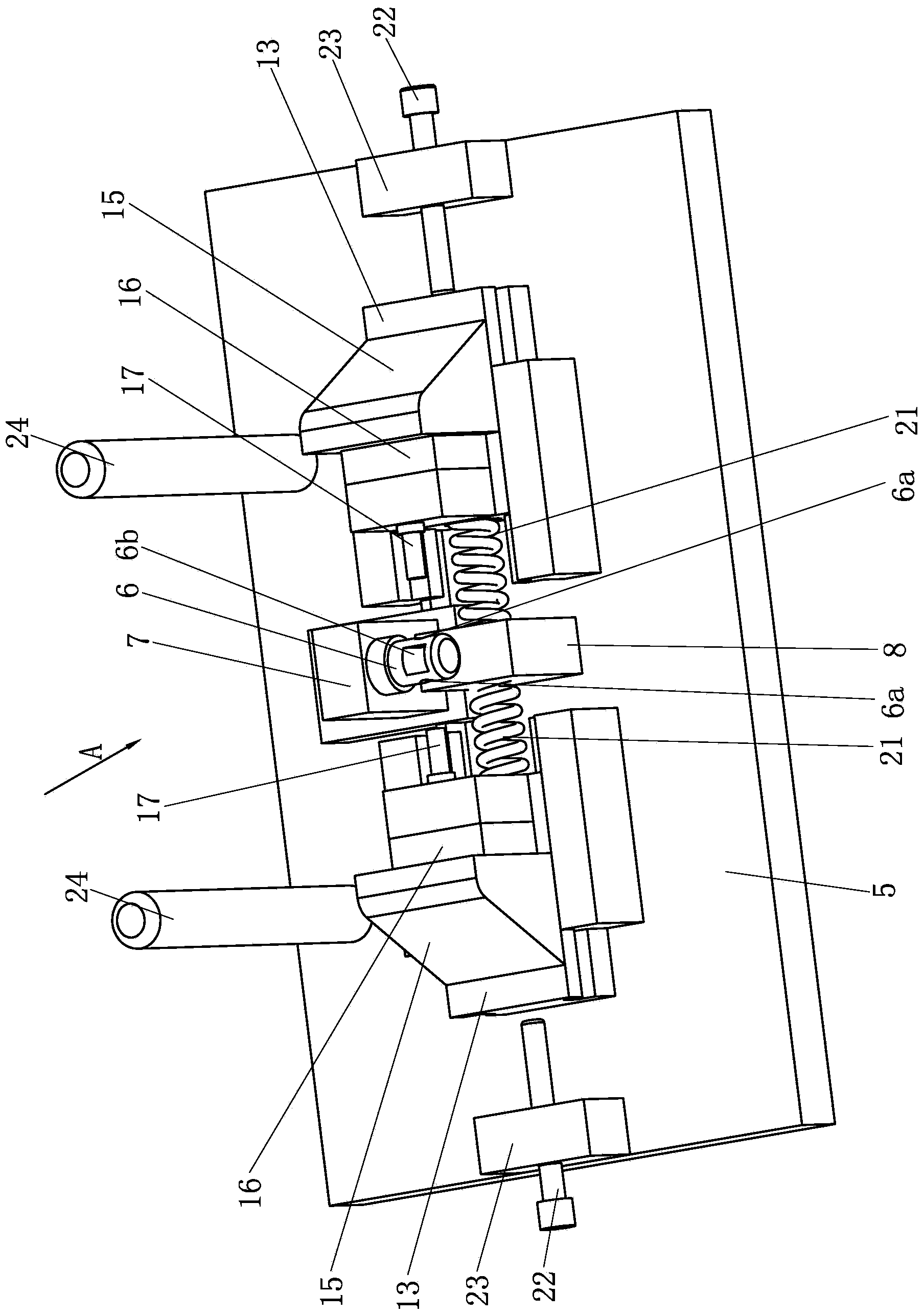
[0029] like figure 2 and 5As shown, a U-shaped tube leg punching tool is mainly composed of a horizontal base plate 5, a U-shaped tube positioning assembly, a side punching assembly, a die, a spring 21, a limit screw 22, a limit block 23, a guide column 24, an inlay Block 25 and adjusting screw 26 constitute. Wherein, a U-shaped tube positioning assembly and two side flush assemblies are provided on the top surface of the horizontal bottom plate 5, wherein the U-shaped tube positioning assembly mainly consists of a U-shaped tube positioning sleeve 6, a connecting block 7, and a first cushion block 8. , The first positioning block 9, the connecting plate 10, the second cushion block 11 and the second positioning block 12 constitute.
[0030] Wherein, the outer diameter of the U-shaped tube positioning sleeve 6 is adapted to the inner diameter of the U-shap...
PUM
 Abstract
Description
Claims
Application Information