Ball head grinding machine for press machines

A technology of presses and grinders, applied in the field of ball head grinders, can solve the problems that the accuracy of stamping parts cannot meet the needs of high-precision machining, the movement of the slider is unstable, and the surface fit is not close, and the machining accuracy is high. , The effect of solving instability and short grinding time

Active Publication Date: 2014-01-01
GUANGDONG LIANXING FORGING MASCH IND CO LTD
View PDF6 Cites 4 Cited by
  • Summary
  • Abstract
  • Description
  • Claims
  • Application Information

AI Technical Summary

Problems solved by technology

[0003] At present, mechanical presses generally have defects such as unstable slider movement, low working accuracy, large wear, and short service life of key parts.
Its instability depends on whether the surface fit between the ball head and the ball bowl in the slider is not tight, and the contact is uneven. Sometimes there may be an error of more than ten microns. The gap between the two is too large or too small to affect the The precision of stamping work of the whole press makes it difficult for the precision of stamping parts to meet the needs of customers for high-precision processing; and when the pressure on the ball head cannot be fully decomposed and exceeds the maximum bearing capacity of the press, the press is extremely It is easy to be damaged, and it is difficult to repair by replacing small parts, with high wear and short service life, which will greatly increase the cost of maintenance

Method used


Image

  • Ball head grinding machine for press machines
  • Ball head grinding machine for press machines
  • Ball head grinding machine for press machines

Examples


Embodiment Construction

[0017] The present invention will be further described below in conjunction with the accompanying drawings and embodiments.

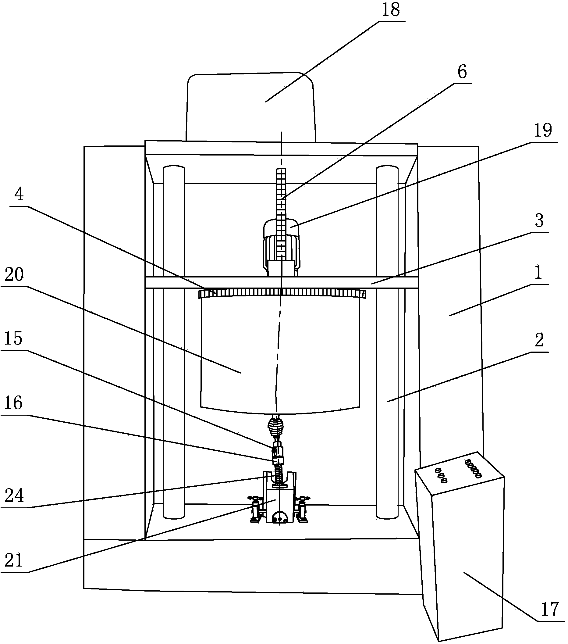
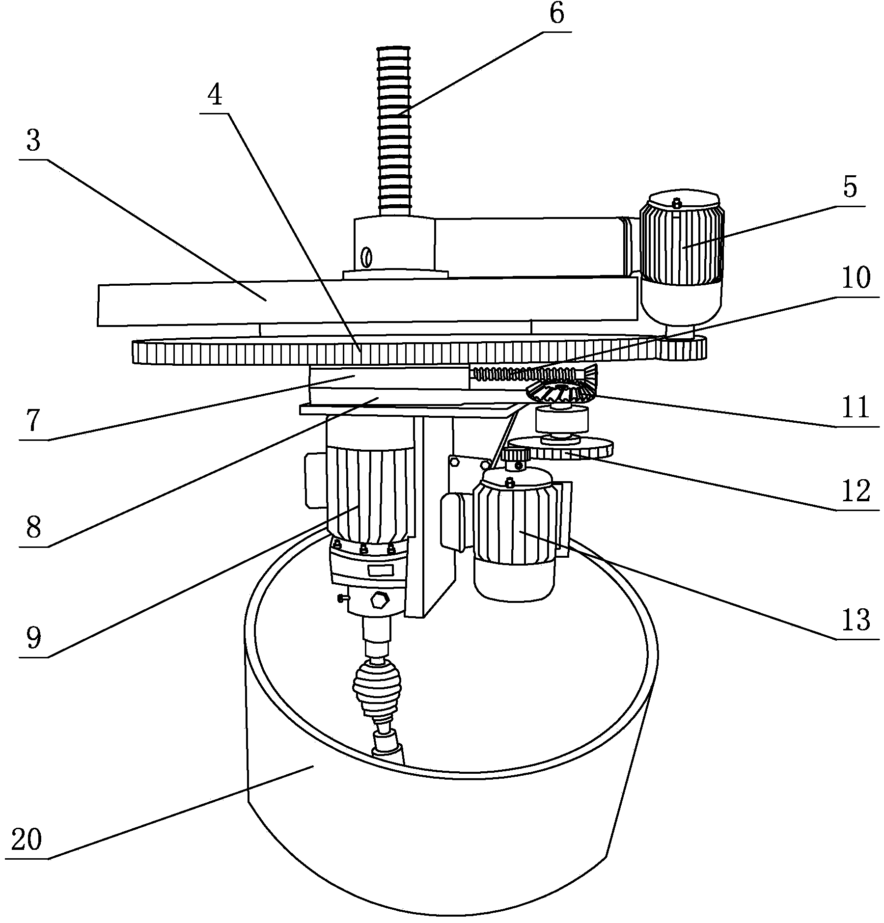
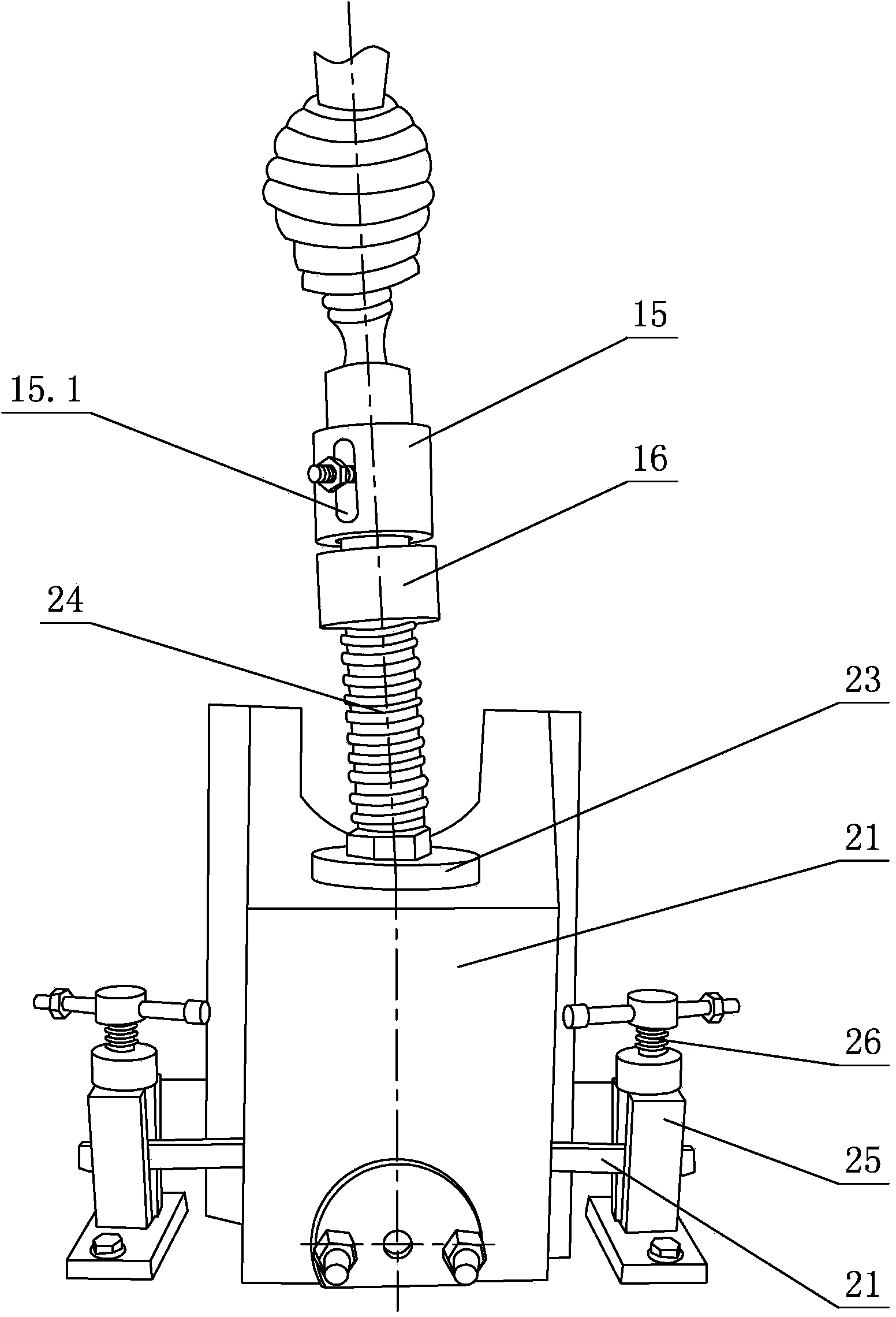
[0018] see figure 1 - Figure 4 , The ball grinder of this press machine includes a fuselage 1 column 2, a lifting screw 6, a rotating power head and a lifting mechanism. The whole of the fuselage 1 is a gantry structure, and the main motor and the lifting plate 3 are arranged on it, and the lifting screw 6 is arranged on the lifting plate 3, and the lifting screw 6 is connected with the main motor drive, so that it can be mounted on the column 2. Move; the rotating power head is provided with a grinding mechanism, and the working position of the grinding motor 9 is adjusted through the grinding mechanism; the upper part of the ball screw 24 is driven and connected with the grinding motor 9, and the lower part is set in the slider 21 and passed through the grinding motor 9. Drive the ball screw 24 to realize grinding in the slider 21; one side of the ...


PUM


Abstract

A ball head grinding machine for press machines comprises a machine body, stand columns, a ball head screw, a rotary power head and a lifting mechanism. A main motor and a lifting board are arranged on the machine body, and a lifting screw arranged on the lifting board which is in driving connection with the main motor through the lifting screw can move on the stand columns. A regulating and grinding mechanism is arranged on the rotary power head, and operation position of a grinding motor is regulated through the regulating and grinding mechanism. The upper portion of the ball head screw is in driving connection with the grinding motor, while the lower portion of the same is arranged in a slider and drives the ball head screw to be ground in the slider through the grinding motor. A clamping mechanism used for fixing the slider is further arranged on a workbench of the machine body. By the ball head grinding machine, errors and shape-position tolerances accumulated in the processing of a ball head are beneficially removed, cooperative compactness between the slider and the ball head is improved, and abrasion between the same at work is reduced, and unsteadiness of the slider at work is solved, so that the slider is enabled to be stable and smooth at work. Therefore, the press machine is higher in pressing precision, longer in service life and high in practicability.

Description

technical field [0001] The invention relates to a ball-end grinder, in particular to a ball-end grinder for a press. Background technique [0002] The ball screw is an indispensable key part in the mechanism that changes the rotary motion into a linear reciprocating motion on the press. [0003] At present, mechanical presses generally have defects such as unstable slider movement, low working precision, large wear, and short service life of key parts. Its instability depends on whether the surface fit between the ball head and the ball bowl in the slider is not tight, and the contact is uneven. Sometimes there may be an error of more than ten microns. The gap between the two is too large or too small to affect the The precision of stamping work of the whole press makes it difficult for the precision of stamping parts to meet the needs of customers for high-precision processing; and when the pressure on the ball head cannot be fully decomposed and exceeds the maximum bearin...

Claims


Application Information

Patent Timeline
Patent Type & Authority Applications(China)
IPC IPC(8): B24B37/025
CPCB24B37/025
Inventor 林国森
Owner GUANGDONG LIANXING FORGING MASCH IND CO LTD
Why Eureka
Try Eureka