Active control method and device for aerofoil drag reduction

An active control and wing technology, applied in the aerospace field, can solve problems such as different technical routes, different formation mechanisms, accelerated motion, etc., to achieve the effects of improving flow quality, better controlling flow separation, and reducing pressure differential resistance

Inactive Publication Date: 2014-01-01
SHANGHAI JIAO TONG UNIV
View PDF7 Cites 13 Cited by
  • Summary
  • Abstract
  • Description
  • Claims
  • Application Information

AI Technical Summary

Problems solved by technology

But the defect and deficiency of this prior art compared with the present invention are: at first, this technology has only a kind of mode of operation, only be used for landing gear to reduce drag and reduce noise when descending, and the present invention can act on the various types of aircraft. In the flying state, it is used for drag reduction of the wings; secondly, although the effect that this technology can achieve is the same as that of the periodic oscillation working mode of the present invention, the effect of drag reduction and noise reduction can be achieved, but their formation mechanisms are different. , the essence of this technology is that the induced velocity is generated downstream of the exposed electrode after the high-voltage and high-frequency electricity is applied to the plasma actuator, and the induced velocity accelerates the movement of the boundary layer fluid, and the essence of the present invention is due to the fact that the piezoelectric device The periodical oscillation of the vortex forms a periodic vortex structure in the wake area to control the flow separation, and the technical route is different

Method used


Image

  • Active control method and device for aerofoil drag reduction
  • Active control method and device for aerofoil drag reduction
  • Active control method and device for aerofoil drag reduction

Examples


Embodiment 1

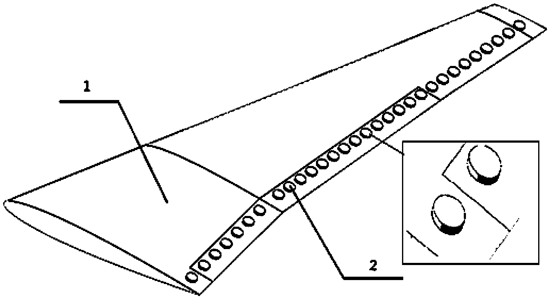
[0024] like figure 1 As shown, the present embodiment is an active control method for wing drag reduction, by uniformly arranging several piezoelectric devices 2 in advance at the trailing edge of the wing 1; then, when the aircraft takes off or flies at a low speed, the piezoelectric devices are controlled 2 is recessed so that the corresponding position of wing 1 forms a dimple, thereby delaying the separation of the boundary layer and reducing the pressure difference resistance.

[0025] Piezoelectric devices 2 are evenly distributed on the rear edge of the wing, arranged in a row, and can be distributed in two rows or even more if necessary. If the wing has flaps or ailerons, they can also be distributed on it; 2 The edge is 5-20mm from the edge of the wing.

[0026] The judging condition of described aircraft take-off is: start to run from the take-off line until leaving the ground, and climb to a safe altitude, which is 25M in my country, and the judging condition of lo...

Embodiment 2

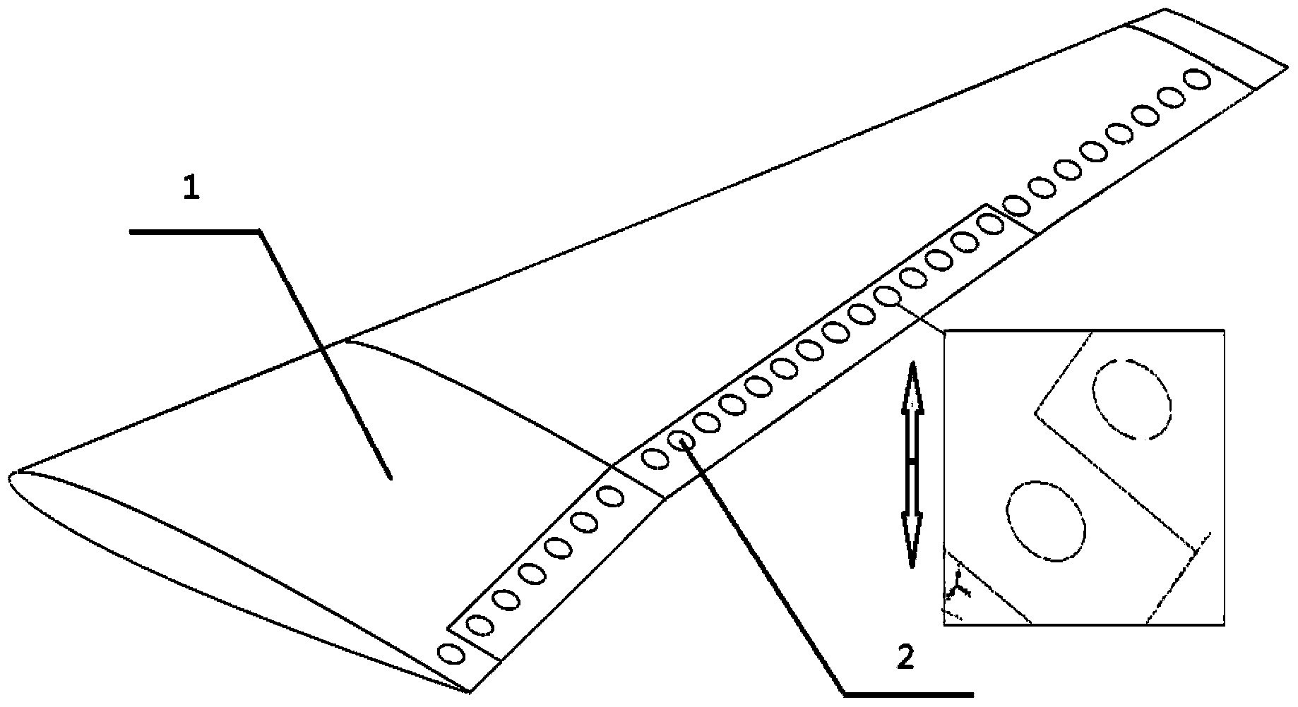
[0030] like figure 2 As shown, when the aircraft is flying at high speed, the piezoelectric device 2 is controlled to protrude so that the corresponding position forms a bulge, thereby reducing the resistance.

[0031] The judging condition for the high-speed flight of the aircraft is: the flight speed reaches more than 900 km / h.

[0032] The specific method for controlling the protrusion of the piezoelectric device 2 is: the motor controls the eccentric wheel 3 inside the piezoelectric device 2 to turn to position 2, and the piezoelectric material 4 is raised and protruded by the eccentric wheel 3 along with the base body 5 .

[0033] The above-mentioned protrusion of the piezoelectric device 2 specifically refers to a protrusion of 1-3mm, and this parameter is determined by the properties of the piezoelectric material 4 as required.

Embodiment 3

[0035] like image 3 As shown, the piezoelectric device 2 is controlled to be in a periodic oscillation mode, so that the wake region of the wing 1 forms a periodic vortex structure to control flow separation.

[0036] The periodic oscillating working mode specifically refers to: the piezoelectric material 4 on the piezoelectric device 2 is in a repeated convex and concave state, and the frequency is 500 Hz.


PUM


Abstract

The invention relates to the technical field of aerospace, and discloses an active control method and device for aerofoil drag reduction. A plurality of piezoelectric devices are uniformly arranged at the trailing edge of an aerofoil in advance, and when an aircraft takes off or flies at a low speed, the piezoelectric devices are controlled to dent so as to enable concave pits to be formed in the corresponding position of the aerofoil, so that the separation of the boundary layer is postponed and the pressure drag is reduced; when the aircraft flies at a high speed, the piezoelectric devices are controlled to be bulged so as to enable bumps to be formed in the corresponding position, so that the drag is reduced; or the piezoelectric devices are controlled to be in the periodic oscillation operating mode, so that the wake zone of the aerofoil is enabled to form a periodic vortex structure so as to control flow separation. The active control method and device for aerofoil drag reduction have the advantages that the aircraft is enabled to actively switch the corresponding drag reduction mode in different flight regimes, and the flight efficiency is improved.

Description

technical field [0001] The present invention relates to a method and device in the field of aerospace technology, in particular to an active control method and device for wing drag reduction. Background technique [0002] Drag reduction is the eternal theme of aircraft design. In recent years, drag reduction technology has developed rapidly, and there are various drag reduction methods. different. For example, the drag reduction effect of dimples is better at low speeds, while the drag reduction effect of bulges is more obvious at transonic speeds, but it will increase resistance at low speeds. These drag reduction methods are all passive, set in advance, cannot be changed, and without feedback, automatic control cannot be realized. [0003] After searching the prior art, it is found that the Chinese Patent Document No. CN102595758A, published on 2012-07-18, records a dielectric barrier discharge plasma trailing edge jet device and method, which involves flow control techn...

Claims


Application Information

Patent Timeline
Patent Type & Authority Applications(China)
IPC IPC(8): B64C3/36B64C21/00B64C23/06
CPCY02T50/162Y02T50/10
Inventor 李伟鹏张屹李斌王建航赵彬彬
Owner SHANGHAI JIAO TONG UNIV
Why Eureka
Try Eureka