Spiral pusher

A screw pusher and pusher technology, applied in the field of packaging machinery, can solve the problems of affecting the efficiency of pushing, unhygienic manual stirring, increasing labor intensity of workers, etc., and achieve the effect of high feeding efficiency and simple structure

Active Publication Date: 2014-01-01
CHINA WEIGHING EQUIP SUZHOU FACTORY
View PDF6 Cites 4 Cited by
  • Summary
  • Abstract
  • Description
  • Claims
  • Application Information

AI Technical Summary

Problems solved by technology

[0002] Nowadays, it is common for the transportation of fine chemical raw materials such as powder, small granular materials, pharmaceutical chemical raw materials, feed, pigments, dyes and even food such as flour, food seasonings, etc. before packaging From the early manual mode to the current semi-automatic and fully automatic mechanical feeding, the screw pusher is one of the feeding machines. One end of the pusher is connected to the storage bin, and the other end is used as the outlet. Through the motor Drive the rotating shaft in the pusher to rotate to complete the material transportation from one end to the other. Currently, the commonly used pusher has a defect that is critical to the material, such as high water content, easy agglomeration, and poor fluidity. When there are materials, bridging will occur in the feeding pipe of the pusher during the pushing process. Once bridging occurs, the operator needs to manually stir the materials in the feeding pipe, which will affect the efficiency of pushing and increase the labor intensity of workers. Artificial stirring is very unhygienic. When encountering toxic or irritating materials, it will pose a threat to the health of workers and pollute the environment.

Method used


Image

  • Spiral pusher

Examples


Embodiment Construction

[0015] In order to enable those skilled in the art to better understand the solution of the present invention, and to make the above-mentioned purpose, features and advantages of the present invention more obvious and understandable, the present invention will be further described in detail below in conjunction with the embodiments and the accompanying drawings of the embodiments.

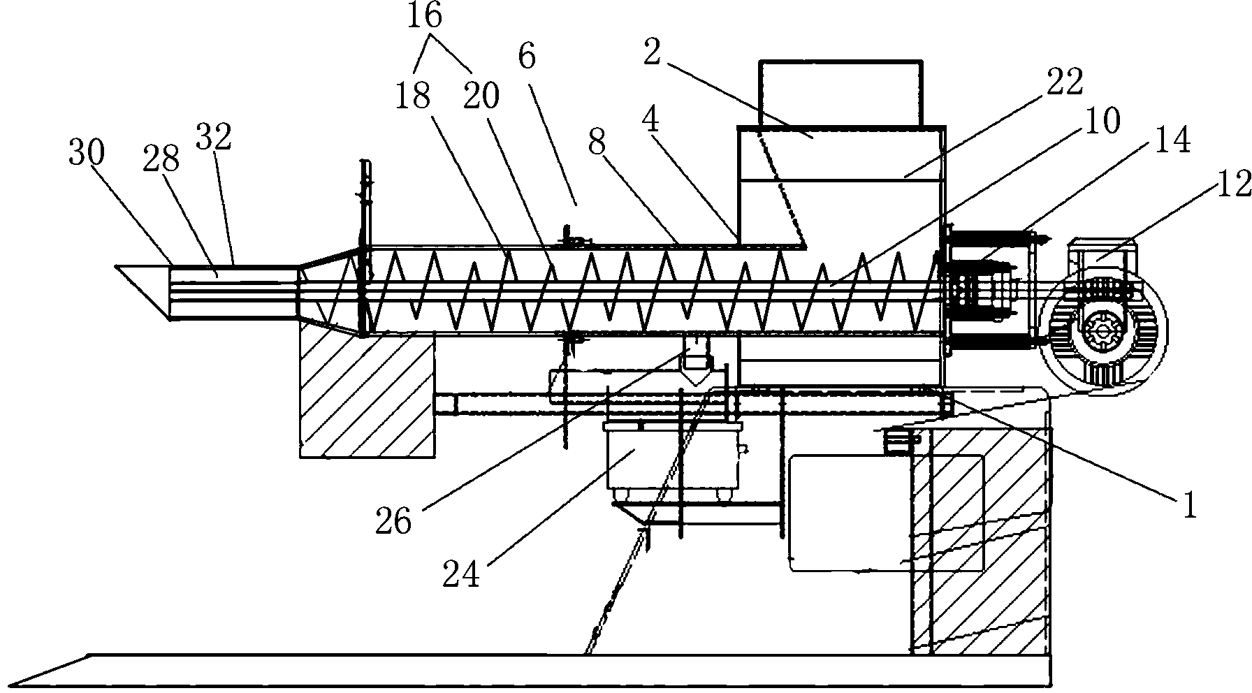
[0016] Such as figure 1 As shown, a screw pusher includes a storage bin 2 fixedly installed on a horizontal workbench 1, and an opening 4 is provided at the lower end of one side of the storage bin 2, and the setting that communicates with the interior of the storage bin 2 through the opening 4 There is a pusher 6 for pushing materials. The pusher 6 includes a hollow feeding pipe body 8, a push rod 10 which is penetrated in the feed pipe body 8 and arranged coaxially with it, and drives the push rod 10 around its own axis. The motor 12 that the line rotates, and one end that the push rod 10 is con...


PUM


Abstract

The invention discloses a spiral pusher, comprising a storage silo and a pusher, wherein a fixed frame of the storage silo is arranged on a horizontal workbench; an opening is formed in the lower end of one side of the storage silo; the pusher which is used for pushing materials is communicated with the interior of the storage silo by the opening; the pusher comprises a hollow feeding pipe body, a push rod and a motor; the push rod penetrates through the feeding pipe body and is coaxially arranged with the feeding pipe body; the motor is used for driving the push rod to rotate around the self-axis of the push rod; one end, rotatably connected with the motor, of the push rod penetrates through the interior of the storage silo, outwards extends out of the storage silo and is rotatably connected with the motor by a bearing frame. The spiral pusher is characterized in that blades which are used for pushing materials are spirally coiled at the outer wall of the push rod. Compared with the traditional pusher, for the materials which are high in water content and poor in mobility and are easily caked and clotted, the spiral pusher solves the problems of bridging or clotting, and has the advantages that the structure is simple and the feeding efficiency is high.

Description

Technical field [0001] The present invention involves a spiral pusher, which is suitable for transportation of materials such as powder, small granular materials, and belongs to the field of packaging machinery technology. Background technique [0002] Nowadays, fine chemical raw materials such as powder, small granular materials, pharmaceutical chemical raw materials, feed, pigments, dyes, and even food such as flour, food seasoning, etc.From the full manual mode of the previous period, the current semi -automatic and automatic mechanical feeding is gradually transitioned. The spiral pusher is one of the feeding machinery. The end of the push is connected to the storage warehouse.Drive the rotation of the rotation in the pushter to complete the material from one end to the other end. At present, the push that is generally used has a dispersion of the material.When the material is material, the phenomenon of bridges will occur in the feeding tube of the push during the push proce...

Claims


Application Information

Patent Timeline
Patent Type & Authority Applications(China)
IPC IPC(8): B65G33/30B65G33/24B65G65/46B65G69/18B65D88/68
Inventor 特雷弗·贝利
Owner CHINA WEIGHING EQUIP SUZHOU FACTORY
Why Eureka
Try Eureka