Textile machine, standby position determining method of driven member of winding unit, and winding unit

A technology for driving parts and standby positions, applied in the field of textile machinery, which can solve problems such as heavy burden on manufacturing operators

Active Publication Date: 2014-01-01
MURATA MASCH LTD
View PDF7 Cites 11 Cited by
  • Summary
  • Abstract
  • Description
  • Claims
  • Application Information

AI Technical Summary

Problems solved by technology

[0007] In addition, when the components of the textile machine are removed for maintenance, it is necessary to reinstall each component at an accurate position, which places a large burden on the operator and the manufacturing worker.
[0008] In addition, this problem exists not only in the upper yarn catching member 30, but is common to all driving parts included in the textile machine.

Method used


Image

  • Textile machine, standby position determining method of driven member of winding unit, and winding unit
  • Textile machine, standby position determining method of driven member of winding unit, and winding unit
  • Textile machine, standby position determining method of driven member of winding unit, and winding unit

Examples


Embodiment Construction

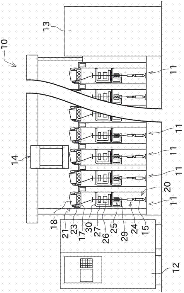
[0038] Next, an automatic winder according to an embodiment of the present invention will be described with reference to the drawings. figure 1 It is a front view showing a schematic configuration of the automatic winder 10 of the present embodiment.

[0039] Such as figure 1 As shown, an automatic winder (textile machine) 10 includes a plurality of winding units 11 arranged in parallel, a machine control device 12, a yarn supply bobbin supply device 13, and a doffing device 14 as main components.

[0040] The machine control device 12 is configured to be able to communicate with each winding unit 11 . The operator of the automatic winder 10 can collectively manage the plurality of winding units 11 by appropriately operating the machine control device 12 .

[0041] Each winding unit 11 is configured to unwind the yarn from the yarn supply bobbin 15, and wind the unwound yarn 16 to the take-up bobbin while moving the unwound yarn 16 laterally. The winding bobbin in the state...


PUM


Abstract

A stepping motor moves an upper-yarn catching member (30) by an amount corresponding to a specified number of pulses. A magnet sensor detects an origin position, which is a reference position, of the upper-yarn catching member (30). A number-of-pulse counting section obtains an actual measurement value, which is the number of pulses necessary for moving the upper-yarn catching member (30) from a target position to the origin position. A drive control section determines a standby position of the upper-yarn catching member (30) in view of the actual measurement number counted by the number-of-pulse counting section, a theoretical value, and the origin position.

Description

technical field [0001] The present invention relates to fiber machinery. Specifically, it relates to a structure for accurately aligning a driving member included in a textile machine toward a target position. Background technique [0002] Textile machines such as automatic winders are equipped with various drive components (components driven by motors, etc.) such as components for catching upper or lower yarns and piecing devices. As a method of driving the driving member, a configuration in which the output of one motor is transmitted to a plurality of driving members using a cam or the like, and a configuration in which a dedicated motor is arranged for each driving member are known. Japanese Patent Application Laid-Open No. 2009-203008 discloses a textile machine having the latter structure. [0003] The textile machine disclosed in Japanese Patent Laid-Open No. 2009-203008 is modularized by dividing the winding unit into a plurality of sections and disposing a control...

Claims


Application Information

Patent Timeline
Patent Type & Authority Applications(China)
IPC IPC(8): B65H54/70B65H63/00
CPCB65H2701/31B65H67/085
Inventor 今村久胜川元谦治
Owner MURATA MASCH LTD
Why Eureka
Try Eureka