Oil-gas well hydraulically-created-fracture expansion visualization experiment method and oil-gas well hydraulically-created-fracture expansion visualization experiment device

A technology of fracture expansion and hydraulic fracturing, which is applied in earthwork drilling, material inspection products, wellbore/well components, etc. It can solve the problems that it is difficult to simulate pore pressure, cannot reflect the influence of drilling disturbance, and cannot realize natural fracture filling, etc. question

Active Publication Date: 2014-01-01
CHINA UNIV OF PETROLEUM (BEIJING)
View PDF3 Cites 127 Cited by
  • Summary
  • Abstract
  • Description
  • Claims
  • Application Information

AI Technical Summary

Problems solved by technology

[0012] In order to overcome the shortcomings of the existing experimental methods, such as the inability to directly observe the fracture propagation path, the difficulty in simulating the pore pressure, the inability to realize the filling of natural fractures, and the inability to reflect the impact of drilling on the disturbance of the in-situ stress field, the present invention provides a hydraulic fracturing fracture for oil and gas wells. Extending the visualization experiment method while providing an experimental setup suitable for the above method

Method used


Image

  • Oil-gas well hydraulically-created-fracture expansion visualization experiment method and oil-gas well hydraulically-created-fracture expansion visualization experiment device
  • Oil-gas well hydraulically-created-fracture expansion visualization experiment method and oil-gas well hydraulically-created-fracture expansion visualization experiment device
  • Oil-gas well hydraulically-created-fracture expansion visualization experiment method and oil-gas well hydraulically-created-fracture expansion visualization experiment device

Examples


Embodiment Construction

[0039] The present invention is described in detail below in conjunction with accompanying drawing and specific embodiment:

[0040] Part 1: Some technical terms involved in this article are explained as follows:

[0041] Visualization: Through real-time observation of things, invisible objects can be observed, and the most direct observation of real-time dynamics of things.

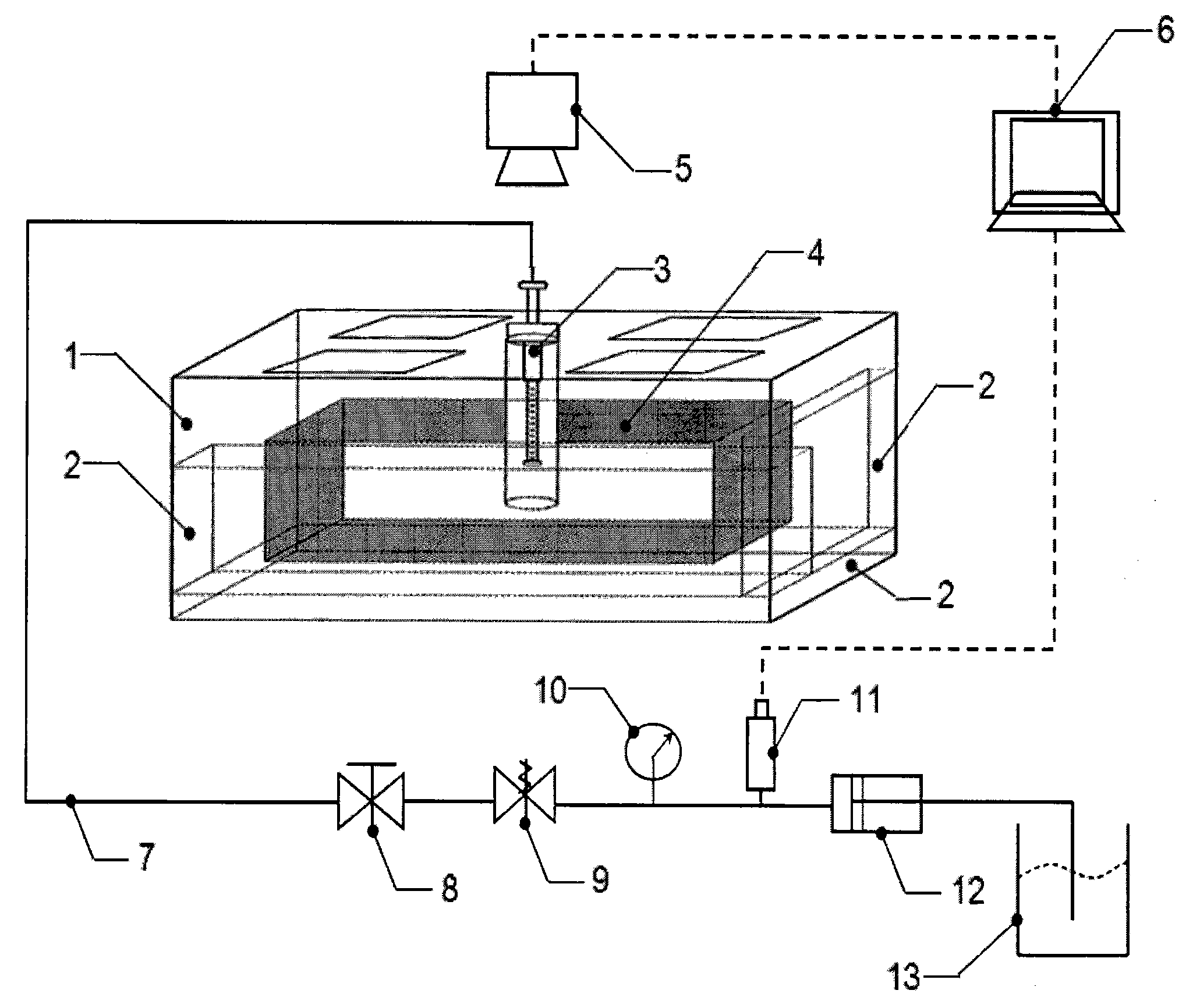
[0042] Hydraulic fracturing: A process in which fracturing fluid is continuously pumped into a simulated wellbore at a large volume through a surface high-pressure pump set, and the rock is subjected to tensile failure or shear failure under the action of high-pressure fluid to form fractures and expand.

[0043] Since the size and construction parameters of the experimental model and the field prototype are quite different, similarity criteria need to be established to obtain meaningful experimental results. The similarity coefficient of the fracturing simulation experiment needs to satisfy the followi...


PUM


Abstract

The invention relates to an oil-gas well hydraulically-created-fracture expansion visualization experiment method and an oil-gas well hydraulically-created-fracture expansion visualization experiment device. The device is composed of a rock sample chamber, a crustal loading unit, a simulation fracturing string, a high-speed camera, a high-pressure pumping unit, a data measuring and collecting unit and the like, and four transparent observation ports are formed on a top cover of the rock sample chamber. The method includes firstly, preparing a flat-plate-type rock sample, performing high-pressure-water cutting to preform a natural fracture, and filling the natural fracture with epoxy resin to form a filled-type fracture; secondly, performing water saturation on the rock sample for 3-5 days, and using epoxy resin to wrap the rock sample after water saturation; thirdly, loading three-axis stress on the rock sample, drilling a borehole under the condition that the three-axis stress is applied on the rock sample, and mounting the simulation fracturing string; finally, connecting a high-pressure pipeline with a constant-flux pump, pumping fracturing liquid, recording a fracture expansion path by the high-speed camera, and measuring pumping pressure changes by a pressure transmitter. By the method and the device, the hydraulically-created-fracture expansion path can be visualized on a plane, and a novel experiment method is provided for studying on a hydraulically-created-fracture expansion mechanism.

Description

technical field [0001] The invention relates to a visual experiment method for hydraulic fracturing crack expansion of oil and gas wells, and provides an experiment device suitable for the method, which belongs to the field of oil exploitation. Background technique [0002] Hydraulic fracturing is a widely used oil and gas well stimulation technology in oil production, especially in low-permeability oil and gas reservoirs and unconventional gas reservoirs such as shale gas and coalbed methane, which have achieved good stimulation effects. Its basic principle is to inject a large volume of fracturing fluid (liquid or gas) into the wellbore through the surface high-pressure pump group, causing formation rocks to form tension or shear fractures under the action of fluid pressure, and finally form fractures with A network of man-made fractures with a certain conductivity. [0003] The research on the mechanism of hydraulic fracturing fracture propagation has always been a hot a...

Claims


Application Information

Patent Timeline
Patent Type & Authority Applications(China)
IPC IPC(8): E21B47/00
CPCG01N33/24
Inventor 盛茂李根生邵尚奇田守嶒陈立强耿黎东
Owner CHINA UNIV OF PETROLEUM (BEIJING)
Why Eureka
Try Eureka